10th July 2011

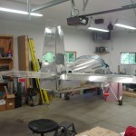
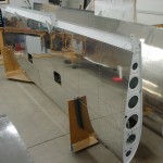
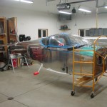
Looks like an airplane

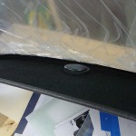
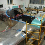
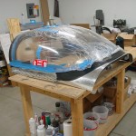
Having picked up some different adhesives last night for the glareshield covering, the first item on today’s agenda was the finished that job.  I had stupidly gotten ahead of myself and removed the inside plastic covering yesterday, in order to be able to work better down in the tight corners at the front.  So, I taped up a bunch of newspaper on the inside of the canopy, to mask the bubble against any overspray.  Feeling sufficiently masked, I sprayed some Super 77 on the glareshield, and a coating on the backing of the fabric, waited the appointed time, and stuck them together.  I did have some troubles with the fabric sticking to the newspaper in the corners, duh…I knew there was a reason I had planned to not put adhesive on the fabric.  Sigh.  In the end, though, it stuck down well, and laid nicely.  It appears that even with my newspaper mask, a couple areas of plexi got a light fogging of overspray, aargh.  I’ve read through the VAF threads about canopy oversprays & cleaning, and sent off for some supplies from Spruce.  This too shall pass, with some elbow grease.

With the fabric in place, I inserted the snap bushing and GPS wire…looking good.

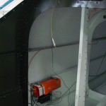
Next task was soldering the ELT connector, so I climbed into the baggage compartment again with tools & supplies.  Easy enough, then I made the LED test tool specified in the manual, which lets you see if the GPS signal is being received by the ELT.  It was, so I buttoned that install up; if I can remember to bring my modular crimpers home from work tomorrow, I’ll be able to put a bow on the ELT installation and cross that off the list.  I also ordered the batteries for the remote units today, having failed to find them at 3 local stores that carry camera batteries.

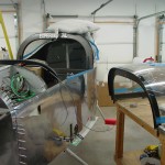
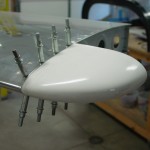
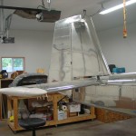
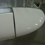
I decided that for whatever reason it was time to set the lengths of the control system pushrods, so I moved things around enough to fit the empennage.  I also primed some spacers and things that needed priming, part related to the empennage attachment.  Bolted on the HS and mounted the elevators.  Decided to fit the HS tips, so I had to do a little bit of trimming, and cleaned up the stepped edge to a nice crisp line with files, before positioning and drilling.  A couple trips in and out of the tailcone had the pushrods adjusted to get full stop-to-stop deflection of the elevators, hitting the travel stops at the elevator end rather than the control column end.  I measured the travel of the elevators to verify it was within spec, and it was.

Since I had the elevators rigged up, I figured I would connect the trim servo and configure it in the VP-X and EFIS.  That was a simple proposition, but I found that the pins for the up/down trim commands into the VP-X needed to be reversed opposite of what’s indicated on the load planning document (ie, 18 down, 19 up).  Once the correct motor polarity was set, the buttons in the software caused the servo to move correctly (“move up” moved the tab down for nose up trim), but the stick switch was running opposite that.  I tested the pins to be sure that I hadn’t reversed them accidentally — I hadn’t, the one marked up was indeed grounded when the up trim switch was pushed.  Swapping the pins at the input of the VP-X allowed it to run as expected.  Not sure what’s going on here, and I’ll be sure to double-check this system later to be sure it’s functioning properly, that I didn’t just have a bad brain day and set it up backwards.  Once it was running right, I measured the travel of the tab to be in-spec, as well.

Finally, mounted the VS and rudder.  Connected the rudder cables to the rudder horn.  Looks like I’ll need the connecting links to be around 2″ long — now, where to find the steel bars that they’re made from…  The rest of the empennage tips will get fitted next, I think; a little fiberglassing practice to close them out, then those surfaces can come back off for storage until final assembly.

Hours: 7 | Posted in Electrical, Wing & Tail Joins | Comments Off
15th November 2010

Clipping the wings

Finished up the fitting of the right flap with a couple off-on cycles of the flap pushrod to get the exit hole just right.  Momentarily hooked up both flaps to actuate them and see if they had correct travel and both retracted flush at the same point.  All seems to be well, though the total travel is about half a degree short of 32* — the spec called out is 32-37.  I’ll have to check what others have had, but I don’t really see a way to increase the travel–changing the pushrod length seems like it would change the up and down points, while leaving total travel unchanged.

Flap fitment complete

After that was completed, the flaps were removed again, and the wings removed and placed back in the cradle.  Flaps and ailerons were put back on for storage–it’s easy to store them there, where they’re less likely to suffer accidental shop damage.  Fuselage and work table pushed to opposite sides of the shop to make room for Allison’s car in the middle.  It’s not by any means a usable shop to accomplish work in, but hopefully will help keep her happy in the mornings.  When the engine arrives, it may need to go in the living room, though…

Shop arranged for the winter

Hours: 1.8 | Posted in Wing & Tail Joins | Comments Off

14th November 2010

Flap fitting

With the chunk of angle for the replacement fuel tank bracket in hand, it was off to the shop to carve it up.  Using the well-fitting left bracket for a template, I traced it in reverse onto the angle for the right bracket, then cut with the bandsaw–bent the angle before cutting the 1″ leg, then shaped to final size with sander and wheel.  Clamped both brackets up to the tank and fuselage, and drilled from inside.  The bottom hole is easy to drill, but the top hole is blocked by both a gear tower tube and the fuel vent line, which meant that the vent line had to come off, and the angle drill be used to make the hole.  No problem; then the brackets are temporarily bolted up and clamped to drill the hole through both brackets.  Once the wings come off, the hole will be slotted and a nutplate installed (after priming…).

Tank attach brackets fit

That task complete, on to the final remaining item before wing removal…installation of the flaps and pushrods, which required cutting the pushrod exit holes.  I started by enlarging the holes in the side and bottom skins with a unibit to 1/2″, then connecting them in a rough shape with a round file.  After the pushrod is attached to the flap and the flap to the wing, the pushrod can be inserted from the bottom and pinned to the actuator arm; then the actuator is moved up and down to check the pushrod hole.  It took several rounds of removal, enlargement of the hole (Dremel sanding drums work well), and re-connection before the hole was right.  I wanted to creep up on it, so as not to have a larger than necessary hole.  Once everything was fitting well, I made a tracing of the hole and transferred that to the other side for a starting point…trimmed it out slightly small to allow for any difference between the sides to be taken up during the fit/enlarge process, but it should make the second side easier.  Finished the rough cutting and hooked up the pushrod before calling it a night.  Hope to get the flap finished and the wings pulled tomorrow, to gain Allison’s car a space in the garage again.

Left flap retracted Left flap and fuselage fit Left flap attached and extended Left flap pushrod hole

Left flap pushrod - retracted Left flap pushrod - extended Left flap pushrod clearance extended Right flap pushrod hole

One word of caution and lesson learned: beware of the little flaps of metal that hang off the aft end of the wings at the inboard edge of the flaps.  When the flap is attached, this piece tends to end up on top of the flap nose…it must be on the bottom side of the flap, or it will be pushed up between the flap and the rear spar and bent when the flaps are raised.  I didn’t check this before raising the left flap, and then promptly repeated the mistake on the right flap…sigh.  The bends mostly came out by hand; I’ll work them a bit more when the wings come off.  At least they’re symmetrically bent now…keeps the plane flying straight!  (builder joke…)

Hours: 3.9 | Posted in Wing & Tail Joins | Comments Off

1st November 2010

One down, one to go

Another attempt to bend the fuel tank attach brackets; clamped the first one tight in the vise using a radiused hardwood block as a sort of mandrel, following the lead of a few who have gone before.  Wailed on that sucker with a big hammer and got about half the required bend; further whacking only served to flex it down into the top of the vise and gouge it up.  Bugger.  Tried soemething different on the second one: used some bits of aluminum angle to fix it in between the vise jaws, with one leg on each jaw, and slowly cranked down.  A couple tries had the bend spot on.  No more material left that’s big enough to make another bracket to replace the gouged up one, so that’ll have to be ordered from Van’s (this being part of the stuff that holds the wing on…).  What’s one more shipping delay, right?

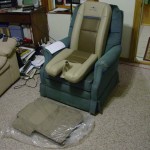
In happier news…the seats arrived this morning!  I was almost out the door for work when the UPS truck pulled up, and offloaded a couple big boxes.  There they sat while I put in a day’s work, and tonight we popped them out to admire.  They turned out nicely, I think.  Back in the box for now for safekeeping.

Lousy picture of a nice seat

Hours: 1.2 | Posted in Wing & Tail Joins | Comments Off

30th October 2010

Wing mounting final tasks

Attempted to finish up the final tasks around mounting the wings tonight, in an effort to get at least one garage bay open for parking again.  First up was drilling the wing root fairings, which turned out to be relatively easy.  The fairing is pre-drilled all along it’s length, and the holes match up with open holes in the wing top skin.  Once in place, the holes are match-drilled into the edge of the fuel tank skin.  Then the bottom fuselage skin is drilled to the wing skin, with the aid of guide lines drawn on the wing skin before mating the wings.  I first drilled all the holes to #40, then enlarged to #19 for the #8 screws.  Once the wings are removed, these holes will be prepped and nutplates attached.

Drilling left wing fairing Right fairing after fitting

The other remaining task was to fabricate and install the F-996A fuel tank attach brackets, which mate with the beefy angle piece built into the inboard nose of each fuel tank.  Cutting and shaping these was straightforward if tedious (due to the 3/16 thickness of the angle), but the bending appears to be the tough part…clamping them in the vise and using a crescent wrench (a la longeron bending) did nothing, nor did whacking them with a hammer and wood block, or attempting to compress them in the vise (as we do in other places when narrowing the spread of a piece of angle).  Reading the typical online sources, it appears I just need to hit them harder, so that’ll be tomorrow’s task.  Tonight, I’ll double-check that everything is done that needs doing before pulling the wings.

Hours: 3.8 | Posted in Wing & Tail Joins | Comments Off

24th October 2010

Activation energy: drilled rear spars

No work on the project for nearly a month, though it’s been near in thought.  Times have been busy at work pushing toward completion of a complete remodel of our audio production studios, and life has happened in other areas, as well.  In the meantime, Vertical Power shipped me the new blank box for the VP-X Pro (the other one is on the way back), and I bought some vise-grip clamps for drilling the rear spars.  That’s about the entire progress that was made on the project; the upside is that the credit card bill this month will be gloriously small.

Tonight I pushed over the next hurdle, hoping that things will mellow a bit for at least a few weeks and allow some work time…the engine and interior should be coming early next month, and the icy season is dead ahead, so I need to get the wings off and restore some garage parking.

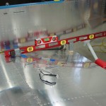
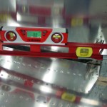
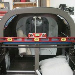
After checking the fuselage for level fore-aft and laterally, I trimmed a block of hardwood to a bit larger than the spacer required for finding the wing incidence, and fine-tuned it’s length with the disc sander.  With the block of wood securely taped to a 4′ level at the correct distance from the end, and a bucking bar taped at the far end to hold it on the wing, I was ready.  Setting the wing incidence was easy; both were very close to start with, requiring only a small adjustment upward, and a push to be sure the rear spar was fully seated in the “hand” of the fuselage.  Clamped down and measured in several locations along the wing, then marked the infamous 5/8″ edge distance on the spar stubs (a piece of scrap filed to 5/8″ made marking easy…I actually cheated for extra safety margin and used a 21/32″ strip, and the width of the marker line made it more like 11/16″…).

Setting wing incidence Double levels for accuracy check

Satisfied with the rigging, I test-fit the flaps as suggested by Van’s in their incidence drilling guide.  Both flaps required filing off a small portion of the inboard nose skin to clear the spar stub for full retraction, but the bottom skin tucked nicely against the fuselage bottom.  Flaps off, I went in and re-read the drilling guide from Van’s.  A couple more measurements, and it’s time to get on with the drilling.  “Nothin’ to it but to do it,” as they say.

The actual deed was done easily.  A long #30 bit and a drill guide made from a block of oak set the pilot holes in the center of the edge-distance box.  Stepped up the holes with a series of drills to final size: #30, #20, #10, .250, .295, then the .3115 reamer for final fit on the AN5 bolt.  A touch of deburring and in went the bolts.  Done.

Left wing margin box Right wing margin box

Left wing drilled Right wing drilled

Left wing temporary bolted Right wing temporary bolted

Hours: 2.8 | Posted in Wing & Tail Joins | Comments Off

26th September 2010

Wing attach

Hit the major goal for this weekend with a short work session: the wings are attached for the first time.  I was able to use a rolling chair with the back removed as a fixture to handle the wings for joining them to the fuselage; along with a sawhorse and a 2×4, it went pretty easily.  I ground the threads down on my four hardware-store bolts to use as drift pins, tapping them in with a rubber mallet when the holes were closely aligned.  After the first fitting, I had to remove the wings to file a bit off the rear spar stubs to remove a touch of forward sweep.  On the second fitting, the forward sweep has been reduced to less than 1/16″ per side…I could call that good, or choose to pull them again and file the stubs some more.  I’ll also read through Van’s wing attach guide document once more to be sure of what happens next.

First round of wing fitting Wings mated for drilling

Hours: 2.1 | Posted in Wing & Tail Joins | Comments Off

23rd September 2010

The end of the wing riveting

Finished up the wing skin riveting tonight (excepting the nutplates for the inspection covers).  I’m clearly not as good of a left-handed riveter, as I managed to put an ugly ding in the right wing bottom skin by slipping off the bar.  Sigh.  Smoothed it out a bit and will either leave it alone or use some filler before paint to level it.

Cleaned the shop up and made room for the wing attach, hopefully coming up this weekend.  The rudder & elevators were removed and stored, then the fuselage was turned into the center of the shop and leveled in both axes.  Measurements were taken, and it appears that there is enough room to fit the wings without having to clear the piles of stuff from the side walls.  The canopy was also removed, as it would hit the garage door opener if opened fully, and having it off will give better access for leaning over to reach the spar bolts.

Wing riveting complete Setting up for the wing attach Fuselage levelled Canopy removed for ease of access

Next step: read up on what needs to be done prior to the wing attach (so far: trim rear spar stub, trim fuel/vent lines, and some sort of marking for the root fairing holes…what else?)

Hours: 2.4 | Posted in Skin Panels, Wing & Tail Joins | Comments Off
29th June 2010

Tail attach

First thing on today’s agenda (well, after the dentist and barber) was rigging the elevators, which meant building the long pushrod that runs from the bellcrank to the elevator horns.  I looked at the plans and added 3/8″ to the pushrod length for fudge factor (easy to remove more, harder to put it back on…).  Cleaned up the ends and taped the fittings and rod end bearings in place, then set the total pushrod length to match the plans.  This turned out the be right one when I put it in the plane: the bellcrank was at it’s neutral spot, as were the elevators.  This is a moving parts moment, so I had to unclamp the elevators for a moment and move the bellcrank while watching the elevators move.  The pushrod was then removed and the ends marked and drilled, with the hole layout done on a piece of tape as a template.  I sloshed primer inside the tube and set it aside to dry for later riveting.

Fitting pushrod, aft end Fitting pushrod, forward end Tape marker for rivet layout Drilling pushrod

The vertical stabilizer was mounted next.  Since this uses the elevator up stop as part of its attachment, that needed to be fabricated and installed (odd that I could not find where the manual says to install this, but clearly it needs to be installed prior to fitting the VS, since it says to drill the VS to it).  Before installation, the VS front spar also needed to be trimmed at an angle to fit.  The installation required some careful, though not difficult, measuring to set the proper angles.  Clamp well, drill, bolt, repeat for the three locations where it is attached to the fuselage.  The tiedown bar differed somewhat from the manual, because I fabricated and drilled it to the aft bulkhead when building the bulkheads.  So rather than drilling the holes in the VS/bulkhead stack and then match-drilling the tiedown bar, I simply back-drilled the VS through the #30 holes in the bulkhead, then enlarged from the outside to 3/16.  This worked well, and the VS was momentarily removed to rivet the tiedown bar to the bulkhead.  To set the location of the front spar, which depends on getting the hinge brackets in a straight line, I ran some string through the hinges and used that as a guide.  I ended up with the VS spar on the back side of the attach plate, which the manual says is kosher.

Elevator up stop drilled VS front spar trimmed Drilling VS rear spar to fuselage VS front spar attachment

Tiedown bar test fit (note string for rudder hinge alignment check) Tiedown bar installed

With the VS attached, the rudder install came next…nothing difficult here, especially as the rudder had already been fitted to the VS during construction of the tail.  I did adjust the bearings for friction-free swing (when building the tail, it is difficult to get the VS rear spar straight, which it is now), and check to see that there was at least 35 degrees of travel on the rudder.

Rudder hung

Final job for the day was fabrication of the rudder stops.  I’ve said this before, but I am very glad to have a bandsaw in the shop now, as it made fabrication of these angles pretty trivial.  I made the rear bit intentionally oversize, to leave a fudge factor for filing down when fitting.  I first fabricated the left stop and fit it to the fuselage, filing away until I hit the required 35 degrees of swing.  Then I simply created a mirror image part for the right side, again leaving some extra material on the rear face for filing.  These turned out nicely, and I’ve left them clecoed in place for now.

Fabricating rudder stops Left rudder stop fitting

A couple pictures of the fuselage with the tail attached…  The book says this is a good time to fit the empennage fairing, but I think I will skip that for now and do it when I do the tips, to keep the glass work together once I’m set up for it.

Overview of tail install Overview of tail install

Hours: 7.5 | Posted in Wing & Tail Joins | Comments Off
28th June 2010

Building the tail

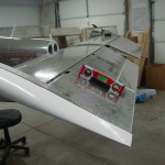
First things first, a plumbing tweak.  I was stumbling around on VAF last night on a completely unrelated topic when I came across a thread about fuel vent routing.  Those lines that I was so happy with had to be adjusted, because I ran them to the top of the bulkhead at a 90-degree angle, which would later interfere with the mouting of the subpanel.  This post has a picture which illustrates the issue.  Not a big deal, I just removed the adel clamps on the aft vertical run, undid the bottom fitting, bent the correct angles at the top, then trimmed the lower portion of the line and re-flared.  The plumbing is really done now…I think.
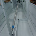
Fuel vent line with correct 45* bend

Nextly, back to work on the aft end of the plane.  I finished drilling up the holes in the horizontal stab, then attached the elevators and fitted the counterweights.  The right elevator is a bit nose-heavy, while the left is almost dead-on balanced.  Supposedly, nose-heavy is the way you want to be before paint, since there is more surface area (thus more added paint weight) aft of the pivot point.  Clamped the counterbalances to the stabilizer in preparation for fitting the pushrod.

Horizontal stab drilled to fuselage Underside of forward HS attach bolts Elevator horns and center bearing

Elevator counterweights bolted in HS and elevators in place

Since the pushrod needs to be fabricated and primed, I took a diversion next to install the control column.  This meant attaching the pivot brackets to the spar, then building the control column on top of them.  This task is complicated by all the various washers to be installed, and I had to fiddle with a few different combinations in order to get it to move smoothly.  After a final test fit and adjustment (these were initially fit during assembly of the center section bulkhead), I greased up the brass bushings and bolted the sticks in place.  I should be able to install the grips and wiring without removing them (crimp the pins, slide the wires down, then insert the pins in the connector), but I’m leaving the cotter pins out for now just in case….it’s s tight space and I’d rather only fiddle with cotter pins in there once.

Control column installed Detail of control column mounting

Hours: 4.9 | Posted in Plumbing, Wing & Tail Joins | Comments Off