6th July 2011

Odd jobs

Trimmed the UHMW block for the top canopy latch, and drilled the holes which bolt it to the canopy frame.  Found a washer that fits the shaft of the latch, and drilled the shaft for a cotter pin, but discovered that the washer’s OD is too large to fit on it; it hits the canopy frame.  I’ll have to dig deeper in the bags, as I must have pulled the wrong washer.  I’m also planning to install the spring modification that others have done, which allows the latch to tuck up parallel to the canopy frame, eliminating the possibility of locking oneself out of the plane if the latch were to slip.

Installed plugs in the open ports of the pitot & static manifolds.  I installed these manifolds to allow for easy expansion in the future, to run lines to a second/third EFIS, autopilot, and whatever new gadget comes along that needs it.  I haven’t found the second long screw I bought to secure these, though…looking like a fresh one from Menard’s.

Installed the center bearing block for the rudder pedals.

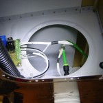
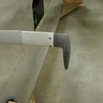
Shaped the upper body of the Gretz pitot tube slightly as needed to fit into the pitot mast, put the nutplates on the mast, and installed it to the wing.  Then, installed the pitot tube to the mast after trimming the pressure line and wires as needed, and wired/plumbed it.  I decided to try using a straight quick-connect union to join the 1/4″ copper line from the pitot tube to the nylon tubing which runs through the wing, since they’re supposed to be OK for all types of tubing.  If it doesn’t work, there’s plenty of room and remaining length on the tubes to do it a different way.  With the pitot installed, I rolled the wing cart over to the fuselage and plugged the left wing in, to verify operation of the heater.  Cooling it off with a cupful of ice water caused the heater to kick on, and the indicators indicated appropriately.  Check.

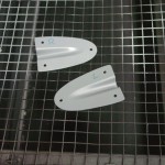
Drilled attachment holes in the rudder cable fairings, then match-drilled them to the fuselage.  I went with one hole in each corner for a total of three; if this proves not enough, it’ll be easy to add two more holes halfway along the sides.  I plan to attach these with blind rivets; easy, and easy enough to remove with a drill if needed later.  Primed the inside surface of the fairings and left to dry.

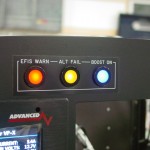
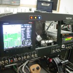
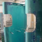
When testing the pitot heater, I had all three of the annunciator lights lit up on the panel, and grabbed a couple photos.  I really like how these LED indicators worked out, even though they were a bit pricey.  They may end up being too bright at night, but with the way they’re wired, it would be simple to add a bright/dim switch, or even a dimmer pot.  And, they should be dark in the normal condition, so it may be a non-issue.  (The camera makes them look brighter than they actually are, too; the hotspots in the photo aren’t apparent to the naked eye.)  I’m still very happy with the panel design & layout; putting that together was, as expected, one of the highlights of the project.

Hours: 3.1 | Posted in Accessories & Mods, Aft Fuselage, Canopy & Frame | Comments Off
13th September 2009

Wing conduits

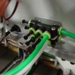
Pulled in the wing conduits; a painless–if rather loud–process.

Wing conduits in place

Hours: 0.3 | Posted in Accessories & Mods | Comments Off
29th August 2009

Pitot mast install

Taking a break from deburring flap parts, I decided to knock out one small task remaining on the wings — install of the pitot tube mount.  I’m not sure yet whether or not I’ll be initially installing a heated pitot (primarily to save the extra cost of the heated tube, though provisions would be made to add it later as part of an IFR upgrade), but I came across a Gretz pitot mount for sale via RivetBangers, and bought it.  This unit has a mounting bracket that installs permanently to the wing, but the mast itself is held in place via four #8 screws, so is removable for service, or simply to keep from banging shins against it.  The install is really pretty easy, once you determine where it’s going to be mounted.  There’s plenty of discussion on that in the forum archives–accuracy generally isn’t affected as long as the pitot is not in the propwash, so the choices come down to things like how close is it to the tie-down rings, tube routing in the wing, etc.  I chose to go with a common location, and the once described in the plans — mounting to the outboard side of the rib just outboard of the aileron bellcrank access plate, on the left wing.

The bracket comes pre-cut, and pre-bent with a joggle to clear the main spar flange.  I fabricated the reinforcement angle that runs fore-aft along the rib out of a trimmed-off piece of stiffener from some control surface or another (I keep a pile of trimmings, anything large enough to reasonably have a chance of use elsewhere for a bracket or whatever).  Cleco clamps hold everything in place and square for drilling, then I drilled the bracket to the spar.  Adjusted the plate to sit even with the rib by using a piece of aluminum sheet to align them, then clamped that in place and drilled the angle to the rib.  On the bench, I marked and drilled the skin-to-bracket hole pattern, and drilled the angle to the bracket.

Clecoed the drilled bracket to the backside of the wing skin using the main spar rivet holes, and back-drilled the holes in the skin, then cut and filed the center mast hole to size, using the mast itself to test fit.  Disassemble and deburr everything, then dimple the holes as appropriate.  I’ll prime these parts along with the flaps, then rivet the bracketry to the rib; the rest will get riveted along with the bottom skin.

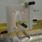
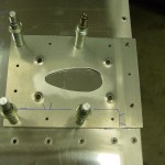
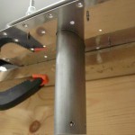
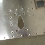
Drilling the pitot bracket to the spar & rib Back-drilling the bracket to the skin Test-fitting the mast to the bracket & skin Holes in skin for pitot attach

Hours: 1.4 | Posted in Accessories & Mods | Comments Off
14th July 2009

LE light lenses and wing miscellany

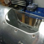
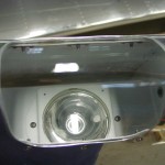
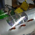
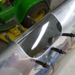
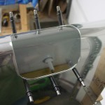
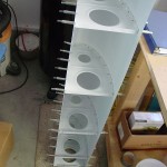
Fit the leading edge light lens to the right wing, using the same process as for the left wing earlier.  Once that was fit (always easier the second time!), and the light bracket mounted in the wing, I assembled both sets of retainer strips that hold the lenses in place–these parts were primed along with the right wing skins.  Used the double-stick tape to attach them to the lenses, and screwed the lenses in place on both wings.  I did install the thin foam weatherstrip tape inside the opening, as listed in the instructions.

Fitting right LE lens Right LE lens installed Right LE assembly Right LE lens installed, inside view

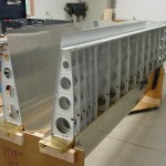
Once both lenses were in place (which completes the LE lights, save for the bulbs) , I flipped the right wing off the stand and into the wing cart, and took apart the stand.  Clecoed the right wing flap & aileron brackets in place, pulled out the aileron/flap gap fairings, and looked at how the flap bracket angles need to be fabricated.  Spent awhile cleaning up the shop from all the projects that have been going on lately…starting to look decent in here again–who knows, might be able get a car or two in here soon!

Both wings in cart

Hours: 3.2 | Posted in Accessories & Mods | Comments Off
5th June 2009

LE light lens fitting

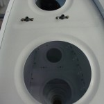
Before dropping the left wing out of the stand (which means turning it nose-down in the wing cart), it seemed like a good idea to fit the lens for the leading-edge light, since it’d be difficult to access in the nose-down position.  Followed the directions that came with the kit, and everything worked out nicely.  You enlarge the holes in the plexi twice after initial drilling, so there is the opportunity to shift them slightly if alignment needs to be fixed.  This one’s not perfect (the holes on the top side ended up being ovaled to tweak the fit), but certainly fine, and the ovals aren’t visible from the outside…once more chance on the other wing.

Trimmed the lens to size with utility knife and bench sander, smoothed with #600 sandpaper, then fit into place using a packing-tape “strap” as described in the instructions.  Drilled, drilled some more, deburred and countersunk, then put together the reinforcing strips that hold the nutplates (prepped these for the right wing install too).  The lens won’t get fit for good until after the next priming session, so that those strips can be primed, but I did install the internal mounting bracket, now that the LE riveting and AOA installs are complete.  Left the bulb out to save it from potential vibration.  I think it ended up looking pretty good.  At some point after it’s flying, I may pursue the “Pete Howell DIY HID modification” to get more light output…but for now, these ought to get the job done.  My plan is to have these on a wig-wag circuit for recognition, as well as taxi/landing steady-on states.

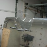
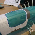
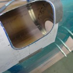
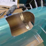
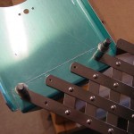
Fitting the plexi lens Plexi lens fit to left wing Plexi lens fit to left wing Light bracket installed in left wing

Hours: 2.1 | Posted in Accessories & Mods | Comments Off
17th May 2009

AOA wing install

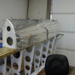
With the leftover Proseal from the left tank, I decided to install the AOA wing components, since they need sealant between the fittings inside the wing and the skin of the leading edge, in which a #60 hole is drilled for the actual port.  The install is fairly straightforward, as AFS provides measurements for properly locating the upper & lower ports.  They are installed at the same chord location, but offset a few inches from each other spanwise.  On the 9 wing, they end up behind the cutout for the leading edge lights, but the AFS guys indicate that’s no problem.  In addition to the two ports, a small hole is drilled in the bottom skin so that a plunger can be inserted to actuate the quick-drain at the bottom of the upper port (allowing any water which may have entered via the upper port to be drained from the system).

Of course, nothing is ever as easy as it seems; the port fittings install with two countersunk screws, which can fit into a #30 dimple (though they’re not actually #30 screws, it seems).  Drilling them was easy (remove the brass barb from the lower port fitting, and use it as a guide to mark the hole locations).  However, having already installed the leading edge to the wing, dimpling those holes was proved interesting.  There is no way to get a squeezer in there, as the end rib is in the way, plus the ports are 4.75 and 7.5 inches inboard from the skin edge.  I experimented with various tools, assemblies of tools, and different ideas without success.  I finally decided to do what is done on the rear spar: dimple, then “ream out” the dimple.  I dimpled to #40 with the pop-rivet dimplers, then used a #30 countersink in a microstop cage, going one step at a time deeper until the screws sat just flush with the skin.  Having already dimpled the skin prevented the countersink from having to remove too much material.

It may not be the perfect way to install these, but they’re in, and it’s what I had available.  Word to the wise: figure out these locations when you have the assembly clecoed together for the first time, and dimple them with a C-frame type tool!  Either that, or buy the #30 pop-rivet dimplers that I now see are available.  I don’t know if these will be needed elsewhere on the plane, but I may toss in a set with my next order of something, just to have around in case.  It’s a solution in need of a problem just like the one I had tonight.

After all that, I even found time to tidy up the shop and put away the various tools that have been laying around.

Hours: 2.1 | Posted in Accessories & Mods | Comments Off
11th April 2009

Leading edge assembly

Clecoed the primed LE components together and test fit on the wing skeletons (again, to be sure they went back together correctly, remembering the trouble I had fitting the left LE the first time).  No problems with the fit, so they’re ready to be riveted.  Need to touch up some bucking dings on the spar before they can be riveted on for good.

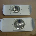
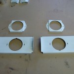
Also riveted the LE light brackets together and fit the reflectors in place.  These won’t go into place until the LE assemblies are riveted onto the spar, to save them from vibration.  I’ll fit the lenses once the LE’s are riveted together, but probably off the spar for easier access.

Hours: 1.9 | Posted in Accessories & Mods, Skin Panels | Comments Off
22nd March 2009

Landing light install

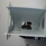
Started work on the Duckworks light kits today, and got all the metal fabrication done, to the point of priming & assembly.  Cut and installed the template on the leading edge assembly (currently clecoed together off the wing), then roughed out the opening with a cutoff wheel in the Dremel.  Finished the opening with vixen file, mill files, Dremel sanding disc, and Scotchbrite wheel in the die grinder.  Cut, drilled and deburred the lamp bracket, drilled the holes in the ribs for the attachment screws/nutplates.  Lookin’ good.

Hours: 3.2 | Posted in Accessories & Mods | Comments Off