Activation energy: drilled rear spars
Hours: 2.8 | Posted in Wing & Tail JoinsNo work on the project for nearly a month, though it’s been near in thought. Times have been busy at work pushing toward completion of a complete remodel of our audio production studios, and life has happened in other areas, as well. In the meantime, Vertical Power shipped me the new blank box for the VP-X Pro (the other one is on the way back), and I bought some vise-grip clamps for drilling the rear spars. That’s about the entire progress that was made on the project; the upside is that the credit card bill this month will be gloriously small.
Tonight I pushed over the next hurdle, hoping that things will mellow a bit for at least a few weeks and allow some work time…the engine and interior should be coming early next month, and the icy season is dead ahead, so I need to get the wings off and restore some garage parking.
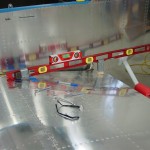
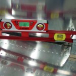
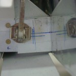
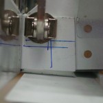
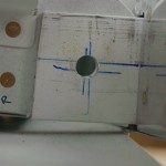
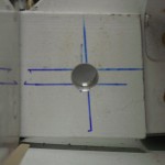
After checking the fuselage for level fore-aft and laterally, I trimmed a block of hardwood to a bit larger than the spacer required for finding the wing incidence, and fine-tuned it’s length with the disc sander. With the block of wood securely taped to a 4′ level at the correct distance from the end, and a bucking bar taped at the far end to hold it on the wing, I was ready. Setting the wing incidence was easy; both were very close to start with, requiring only a small adjustment upward, and a push to be sure the rear spar was fully seated in the “hand” of the fuselage. Clamped down and measured in several locations along the wing, then marked the infamous 5/8″ edge distance on the spar stubs (a piece of scrap filed to 5/8″ made marking easy…I actually cheated for extra safety margin and used a 21/32″ strip, and the width of the marker line made it more like 11/16″…).
Satisfied with the rigging, I test-fit the flaps as suggested by Van’s in their incidence drilling guide. Both flaps required filing off a small portion of the inboard nose skin to clear the spar stub for full retraction, but the bottom skin tucked nicely against the fuselage bottom. Flaps off, I went in and re-read the drilling guide from Van’s. A couple more measurements, and it’s time to get on with the drilling. “Nothin’ to it but to do it,” as they say.
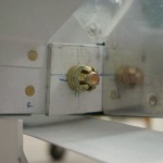
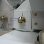
The actual deed was done easily. A long #30 bit and a drill guide made from a block of oak set the pilot holes in the center of the edge-distance box. Stepped up the holes with a series of drills to final size: #30, #20, #10, .250, .295, then the .3115 reamer for final fit on the AN5 bolt. A touch of deburring and in went the bolts. Done.
