30th July 2008

Wing ribs & tie-down bars

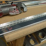
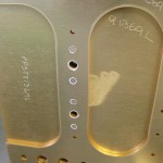
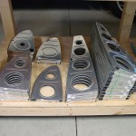
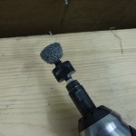
Allison put in another hour on the bench grinder, helping to debur wing ribs.  We’ve made it through more than half the stack — only the large pile of main ribs remains.  Taking a cue from the mini-scotchbrite tool that can be made for the Dremel, I came up with a handy item for deburring the inside flanges of the ribs, especially the little finger bits on the leading edge nose.  I used the top half of a 1″ scotchbrite wheel that had split in half, fit it to the screw mandrel in the die grinder, and shaped it into a wide taper profile by turning it against the 6″ wheel on the ginder.  Just like the Dremel method, on a larger scale.  The secret is that after it’s shaped, unscrew it and put it back on upside down–so the wide part is at the top, tapering inward toward the body of the grinder.  I found this profile worked extremely well for deburring rib flanges, as it allows you to get the “cutting edge” into the bend radius; then you can raise or tip the grinder to debur the slots.  You can also use the blunt end of the wheel for deburring tooling holes and such, like the vent line holes on the tank ribs.  I still used the Dremel device for the corner slots, as the die grinder tool is too big to fit in there.

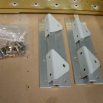
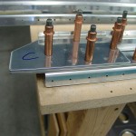
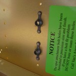
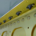
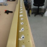
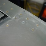
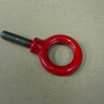
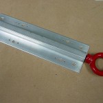
Shipment from Cleaveland Tool arrived this afternoon with new abrasive supplies, and tie-down parts.  I ordered their set of pre-tapped tie-down bars and power-coated rings–I had made a harmless goof in the fabrication of the tie-down bars and this gave the chance to fix it.  (Be sure which side of the spar is the top side when bolting the match hole in the extrusion…I put them both upside down, which didn’t look like it would be a big deal, it just means the threads would be recessed a bit farther into the wing than intended.  The part I wasn’t sure about was whether the tie-down rings would be able to bottom out, and thus tighten, in the threads before starting to rub on the wing skin.)  In any event, I would have bought the nice red forged rings eventually anyway, so this presented the opportunity to get all that and finx my little oops, plus it means I don’t have to buy a tap-and-die set (which would end up being an extra when I eventually figure out a way to move tools down from home), which probably saves something in the long term anyway.  I’m happy.

I have been enjoying Bob Collins’ Oshkosh coverage, as I’m not able to make it over this year, due to work schedule (someone decided we needed a motivational-speaker “retreat” on one of the days I had hoped to use for OSH), plus unexpected expenses arising from the storm damage.

Hours: 3.4 | Posted in Spars & Skeleton | Comments Off
29th July 2008

Wing rib deburring

Spent the evening decompressing in the shop and deburred some wing ribs.  Finished all the lightening holes with assorted 1″ and 2″ scotchbrite wheels in the drill press and die grinder.  Finished the leading edge ribs (non-tank) with the bench grinder and the 6″ wheel.  I used a handy tip I read from another builder about deburring the silly little finger notches — take a section of worn-out 1″ wheel and cut it into quarters, put a piece onto a Dremel screw mandrel, and shape it into a cone against the 6″ wheel on the grinder.  This creates a custom tiny scotchbrite tool for the Dremel–it actually works quite nicely, though the tiny piece wears down after a half-dozen ribs or so, and needs to be replaced.  No biggie, as I have two worn-out 1″ wheels.  More on order from Cleaveland to replace them, along with a bundle of hand pads for primer prep, a #12 bit (I discovered that the #12 slot in my bit set actually held a #11).  I also ordered a batch of Stewart Systems priming supplies from RFS.

Allison helped for an hour deburring ribs on the bench grinder.

Hours: 2.8 | Posted in Spars & Skeleton | Comments Off
27th July 2008

Tie-down bars & Rear spar prep

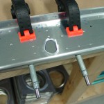
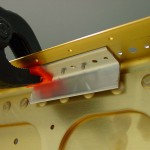
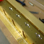
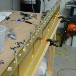
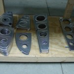
Fabricated and drilled the tie-down bars to the front spars.  Drilled & attached the nutplates for the aileron bellcrank brackets.  I used a short bolt stacked with washers to hold a nutplate in place as a jig for drilling.  The bars are off to await priming, which I intend to do as a batch with the rear spar components; they also need to be tapped for the 3/8 bolt threads.

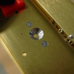
Prepped the rear spar components: drilled, deburred, countersunk and dimpled as appropriate (above the doubler at the inboard end, since these dimples would be nearly impossible once the doublers are riveted in place; their thickness prevents access with the dimple dies).  I need to order some more primer and scotchbrite to move forward on these; now there’s nothing to do besides start prepping wing ribs.

Hours: 5.7 | Posted in Spars & Skeleton | Comments Off
25th July 2008

Weathering the storm

Finally back to the project again, after an insane two weeks. July 10 brought severe weather moving across the area, a tornado 3 miles east of here, and associated straight-line winds. Those winds brought down 5 trees, blew out half the porch windows, and downed our power pole. Five days and one large electrician’s bill later, we were back on the grid. Spent considerable time with a chainsaw cleaning up; thankfully neighbors & friends came by to help out as well. That week was followed up by a 60-hour week on the job, so nothing much was accomplished besides work, eat, and sleep. Today, I was able to temporarily fix up the ignition system on the garden tractor (will need a new coil, but it’s operable), so the light was green for a return to the plane.

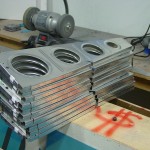
So, the front spar prep is basically complete, with the riveting on of the two nutplates at the inboard end of each spar. Van’s sent out the six missing nutplates after I emailed them about the inventory. Next is prep of the rear spars, then the massive rib deburring task begins.

Hours: 0.1 | Posted in Spars & Skeleton | Comments Off
8th July 2008

More spar nutplates

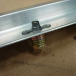
Finished drilling, deburring, countersinking, priming, and riveting the fuel tank attach nutplates to the lower flange of both spars.  Also attached the 24 access panel nutplates.  The next step in the manual is to attach the center section nutplates, which go on the spar web near the inboard end of each spar, two per wing.  These, I discovered, are the K1000-4 nutplates which were omitted from the kit when I received “Q Bag 1923″ instead of the “Bag 1923″ listed on the packing list.  Email sent to Van’s noting the inventory discrepancy.  Beyond that is the fabrication & attachment of the tie-down blocks.  I have no tap to cut the threads, so that might wait for now.  I did drill out the massive spar rivet that had been set in one hole meant for a bolt mounting the tie-down block–I guess someone at the factory just got carried away with the riveting.  For now, I guess I’ll have to get down to business and start prepping ribs.  Which reminds me…I need to order more scotchbrite supplies and some primer.

Hours: 2.4 | Posted in Spars & Skeleton | Comments Off
7th July 2008

Spar nutplates continued

More drilling, countersinking, and deburring of spars for fuel tank & access plate nutplates. Completed the bottom of the right spar, and about half of the bottom left.  No pictures since it looks the same as yesterday’s work.

Hours: 1.9 | Posted in Spars & Skeleton | Comments Off
6th July 2008

Spar prep: nutplates

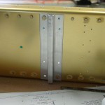
Began work on the wing kit today, by drilling and riveting half of the tank attach nutplates. Completed the upper side of both spars. I made a jig for countersinking the #8 screw holes out of a cut-off piece of 1×1 angle by drilling a nutplate to it, and putting a #30 hole (to match the countersink pilot). Clecoing it to the spar didn’t work, as it blocked the countersink cage, but dropping two rivets in the nutplate attach holes, then fixing the jig in place with a clamp, worked well. This reduced the chattering of the countersink cage, since the pilot doesn’t run out of material as it would if you had only the thickness of the spar flange. It produced decent holes.

The process – ream the rivet holes to #40, deburr the bottom, countersink the top. Attach the jig and countersink the center hole for the screw, and debur the bottom. Spot prime with a Q-tip dipped in primer. When dry, cleco one leg of each nutplate, rivet the opposite side, then remove clecoes and squeeze the second rivet.

There are 62 tank attach screws/nutplates on each spar, plus inspection plate holes on the bottoms. I also discovered (looking ahead) that one of the holes that should be open to bolt on the tie-down fixture is filled with a rivet on the left spar. I assume this will just get drilled out, but that’s a massive rivet.

Hours: 3.8 | Posted in Spars & Skeleton | Comments Off
5th July 2008

Wing inventory complete

Inventoried the remaining portion of the wing kit this evening. No damage at all, and only one minor discrepancy on the inventory–the packing list includes a hardware bag named “Bag 1923,” but I received “Q Bag 1923.” The difference is that “Bag 1923″ is supposed to include 6 K1000-4 nutplates that are not included in the “Q Bag.” The bag is just labelled as “misc. hardware,” so I’m not sure whether this is a goof, or a change.

Lots of ribs are stacked up to await their deburring, and the large parts are stored in the spar box for now. I’ll have to come up with a decent way to store the skins and long angles, as having the crates in the shop isn’t going to work.

Hours: 1.3 | Posted in Wings | Comments Off
1st July 2008

Wing hardware

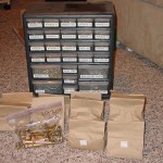
Killed some time this evening by opening up the sack of wing hardware and sorting through it.  That’s a lot of rivets.  Also sorted the bulk rivets into the drawer organizer and labeled it with the trusty P-touch.  The rest of the hardware will stay in their bags, since they seem to be grouped by area (ailerons, flaps, fuel fittings, etc), which is logical enough–and keeps me from buying another organizer!

Hours: 1.9 | Posted in Wings | Comments Off
1st July 2008

Elevator fix-it

Today I received a reply to my query to Van’s regarding the twisted elevator problem. From Ken Scott:

This is a significant twist, but we have no test data that would enable us to know how much twist is too much. We haven’t built elevators with different twists and flown them, in other words.

We know there are RVs flying with twisted elevators and nothing bad has happened, but again, how much is too much?

You have two options:

1. rebuild the elevator to the intended configuration. This doesn’t necessarily mean building an all-new elevator — just drilling out rivets until you can straighten the one you have would probably work. No flight risks here — we know straight elevators work.

2. fly it the way it is and let the airplane tell you if it needs to be changed. Problems would most likely show up as rigging/trim problems rather than structural ones. Some risk here, as we really can’t say what the flight characteristics might be

Pretty much what I expected to hear, though perhaps not what I was hoping to hear. So, in reading that and thinking about it, I decided to take a look and see how difficult it would be to fix the thing, rather than hoping it would work and (possibly) having to fix it later. I’m a semi-reformed perfectionist, and every once in awhile I have these tendencies. (If there’s one place I don’t mind having perfectionist leanings, it’s in the building of the plane…)

Out to the shop I went, and did some checking at various places on the table (which I’ve come to believe isn’t perfectly flat, and is probably the cause of at least some of the twist), to determine how and where the twist was built in. I drilled off the skin from both the root and counterbalance ribs first. Not enough. The trailing edge had to come undone too, and I believe this is what happened: the skin closure at the trailing edge wasn’t perfectly even when drilled originally, rather the top sheet was offset to one side, which caused the whole thing to twist.

In case there’s a question, applying heat to Proseal does not cause it to become more fluid; it just gets hot. I tried this on some scrap angle which had the stuff on it from when I sealed the TE’s, with no luck. There wasn’t enough “give” in the Prosealed trailing edges to let it move enough, so I ended up using a thin flat ‘blade’ of sorts to split the bottom skin from the AEX wedge. I didn’t spread it enough to disturb the ends of the stiffeners which had been sealed together, nor did I disturb the top skin.

Next I clamped the whole thing to the table quite well, used a 4′ level and spare angle to prove that it was flat, and proceeded to re-squeeze rivets into the trailing edge, using the same approach as used the first time. Also squeezed a few rivets in each end rib. Initial testing after the clamps were removed looked promising, so I squeezed the rest of the rivets, and pulled the blind ones (which I had to steal from the wing hardware, so I suspect I’ll need to order some extras). Yes, my elevator has one more blind rivet than it did before, because I got carried away and drilled out an inaccessible rivet (one of the counterbalance skin to elevator skin rivets on the inside of the end rib)…the other four are at the hard-to-buck ends of the ribs.

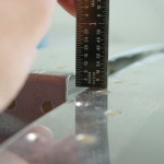
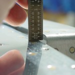
Test time…I expect the problem to be improved but not perfect. Cleaned up the table and brought the HS back up, the proceeded to hang both elevators. Clamped the counterbalances in trail, clamped the long angle across both elevators. In my hand, it looked mighty close… Rested the center of the angle (behind the control horns) on the shop chair, and took the ruler in hand to compare the two sides (the chair doesn’t go high enough to get the counterbalances flush, so I measured the height of the counterbalance nose above the HS skin. Left…6/32″. Right (rebuilt)…6/32″.

I’d call that fixed. Almost three hours, but well-spent both in solving the problem, and in regaining my confidence.

(despite how it looks in the photo, the right one did measure around 6/32″; I was supporting the camera on the HS with one hand, which caused it to tip down and increase the gap.)

Hours: 2.8 | Posted in Elevators | Comments Off