Tail attach
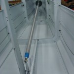
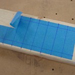
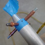
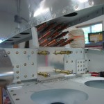
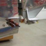
Hours: 7.5 | Posted in Wing & Tail JoinsFirst thing on today’s agenda (well, after the dentist and barber) was rigging the elevators, which meant building the long pushrod that runs from the bellcrank to the elevator horns. I looked at the plans and added 3/8″ to the pushrod length for fudge factor (easy to remove more, harder to put it back on…). Cleaned up the ends and taped the fittings and rod end bearings in place, then set the total pushrod length to match the plans. This turned out the be right one when I put it in the plane: the bellcrank was at it’s neutral spot, as were the elevators. This is a moving parts moment, so I had to unclamp the elevators for a moment and move the bellcrank while watching the elevators move. The pushrod was then removed and the ends marked and drilled, with the hole layout done on a piece of tape as a template. I sloshed primer inside the tube and set it aside to dry for later riveting.
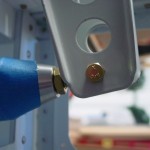
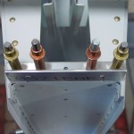
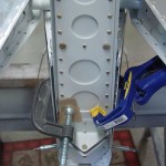
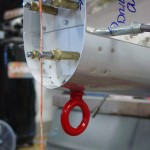
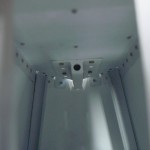
The vertical stabilizer was mounted next. Since this uses the elevator up stop as part of its attachment, that needed to be fabricated and installed (odd that I could not find where the manual says to install this, but clearly it needs to be installed prior to fitting the VS, since it says to drill the VS to it). Before installation, the VS front spar also needed to be trimmed at an angle to fit. The installation required some careful, though not difficult, measuring to set the proper angles. Clamp well, drill, bolt, repeat for the three locations where it is attached to the fuselage. The tiedown bar differed somewhat from the manual, because I fabricated and drilled it to the aft bulkhead when building the bulkheads. So rather than drilling the holes in the VS/bulkhead stack and then match-drilling the tiedown bar, I simply back-drilled the VS through the #30 holes in the bulkhead, then enlarged from the outside to 3/16. This worked well, and the VS was momentarily removed to rivet the tiedown bar to the bulkhead. To set the location of the front spar, which depends on getting the hinge brackets in a straight line, I ran some string through the hinges and used that as a guide. I ended up with the VS spar on the back side of the attach plate, which the manual says is kosher.
With the VS attached, the rudder install came next…nothing difficult here, especially as the rudder had already been fitted to the VS during construction of the tail. I did adjust the bearings for friction-free swing (when building the tail, it is difficult to get the VS rear spar straight, which it is now), and check to see that there was at least 35 degrees of travel on the rudder.
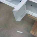
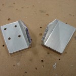
Final job for the day was fabrication of the rudder stops. I’ve said this before, but I am very glad to have a bandsaw in the shop now, as it made fabrication of these angles pretty trivial. I made the rear bit intentionally oversize, to leave a fudge factor for filing down when fitting. I first fabricated the left stop and fit it to the fuselage, filing away until I hit the required 35 degrees of swing. Then I simply created a mirror image part for the right side, again leaving some extra material on the rear face for filing. These turned out nicely, and I’ve left them clecoed in place for now.
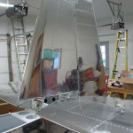
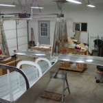
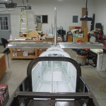
A couple pictures of the fuselage with the tail attached… The book says this is a good time to fit the empennage fairing, but I think I will skip that for now and do it when I do the tips, to keep the glass work together once I’m set up for it.
