27th February 2011

Beginning panel electrical

I often find myself bouncing around the project lately, where I may be working on three little jobs at once in different parts of the shop…waiting for paint to dry on a couple things, for instance, while drilling something and wiring something else.  So when I sit down at the end of the day to write these logs, it’s sometimes challenging to think back and remember everything I did that day.  Pictures help, but I’ve had a bad time remembering to take a photo of every little job, too.

Today’s work…

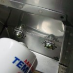
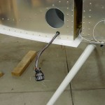
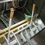
  • Riveted the right cabin heat control bracket to the vent bracket, which was then riveted to the side skin.  Installed the control cable and secured it, which required some modification to the firewall passthru, as the cable was just slightly loose in the eyeball.  I used a flat file to shave just a bit off the flat side of each ball halve, which allowed it to get a firm grip on the cable and secure it in place.  Cut the casing and cable to length and assembled.  Installed the right side vent nozzle.

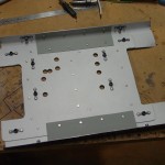
  • Traced the spare round-gauge hole, and the autopilot head hole, onto scrap stock and cut it out to make filler panels for those cutouts, since they will not have instruments installed in the until phase two of the panel.
  • Fabricated angles for mounting the radio stack to the panel.  Waiting to drill them to the panel until the radios are in hand, in case the width of the trays is a bit off of the width of the panel cutout.
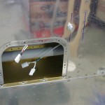
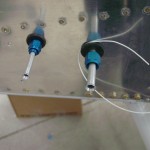
  • Cut a hole in the subpanel behind each EFIS screen to pass the wiring harnesses and pressure tubing.  Also put a hole in the lower right subpanel for the wiring feeds to the switches on that side of the panel, in addition to the hole that’s already made for running cable to the dimmer module.  I have a couple sizes of nice rubber grommets from McMaster, in addition to an assortment of snap bushings that I bought from Van’s awhile back; finding the right size for a particular hole is easy.

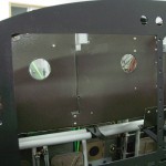
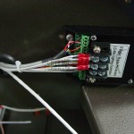
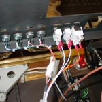
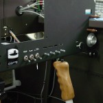
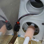
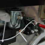
  • Wired up the dimmer pots and interior light switches, then dropped the panel in to test them out.  While the panel was in, I ran wire for the accessory power jack and the music input jack next to it (though this wire may end up being a placeholder, if this wire is already in the harness from Stein).

  • Ran a wire to each Pmag for the serial port connection.  I will bring each of these to a jack on the subpanel for ease of connection with the computer utility.  The rear-mounted APRS transmitter will have a similar jack on the baggage bulkhead for programming.
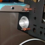
  • Test-fit the CO/SpO2 sensor.  Can’t use washers on these screws, because the mounting holes on the piece are too close to the protruding bezel.  Decided I need to get some #10 capscrews for the throttle quadrant mount to the panel, which should work better than bolts due to clearances (sockets were getting wedged in place).

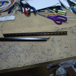
  • Cut the plastic U-channels for the switch backlights, and painted them black.  Cut LED strips to length for each piece of channel (3 total), and soldered leads to them.  After testing them, it looks like another layer of paint will be necessary; the light bleeds through the sides of the channel.

Hours: 6.9 | Posted in Cabin & Interior, Electrical | Comments Off
26th February 2011

Cabin work

Spent the day working on various items, mostly in the cabin area.

  • Hooked up the Garmin GPS 18x-5Hz to power and a computer to program & test it out.  Solid lock even inside the house.
  • Printed real labels for the various wires I had labelled with tape after I ran out of label stock.
  • Installed a connector on the #2 OAT sensor, installed it in the wing, and added connectors to the wing end of the OAT cable for both sensors.

  • Drilled the #2 EFIS tray to the panel, the #1 tray will come with the avionics order…hopefully next week!
  • Deburred and primed the panel and riveted the top angle on, after removing a bit of one ear on the angle to allow for the #1 EFIS tray.
  • Riveted the canopy seal support angles to the subpanel.
  • Removed the right side panel-subpanel  rib as I did earlier on the left; though I spaced the radio stack to not interfere with the rib, the angle to mount the stack would overlap the rib, and there would be no clearance for the mounting nuts.  This could be shortened by the thickness of the angle and mounted behind it, or (easier) moved to the right by 3/4″ of an inch of so.
  • Added nutplates to the panel flange, and the subpanel bracket, to bolt the throttle quadrant mount to.  I’m making a conscious effort/decision to use nutplates under the panel, and have bolt/screw heads face down, so that future maintenance will be easier.  Also any electrical connection that must be made with solder (such as master and starter switches) will have a connector inline, to allow the component to be removed and serviced on the bench, rather than soldering in situ, laying on my back working over my head.
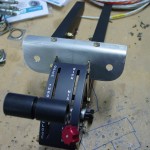
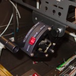
  • Fabricated a bracket that straddles the throttle quadrant, to allow mounting of the fuel purge and center cabin heat controls on either side.  Painted and temporarily installed with the quadrant to work out cable routing.  Quadrant and bracket are mounted via the same bolts, and the bracket dresses out the quadrant install well, I think.

  • Finished installing the firewall eyeballs for the throttle, mixture, and center cabin heat controls.  These buggers are time consuming…but only two left (purge & alt air).

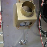
  • Fit the center cabin heat cable and figured out the cable route.  Put the right seat in to sit and work out a location for the right-side heat cable.  Decided to put it under the right air vent, against the sidewall.  So, fabricated a mounting bracket and painted for installation tomorrow.
  • Riveted the left side vent bracket in place and installed the vent.  (Right side tomorrow, after the heater cable bracket is attached to it.)

Passed 1200 hours in this session.

Hours: 9.1 | Posted in Cabin & Interior, Electrical | Comments Off
22nd February 2011

Little things

Panel placards arrived today, they look good.  All the holes are perfectly aligned with the panel cutouts, so the drawings and CNC cutting worked well on both ends.

Primed & painted a few small pieces for installation in the next session.

Hours: 0.8 | Posted in Cabin & Interior | Comments Off

21st February 2011

Panel & lights

Cleaned up the bench and found the countersink cutter, so I countersunk the vent brackets and panel top, then pulled everything apart for deburring and primer.  The panel won’t be primed/painted yet, as it will need more drilling and such to mount the avionics.

Wired the map lights and baggage lights to the dimmer module, temporarily connected the dimmer pots, and put some power to it; it’s fun to see things light up.  I also clamped an LED strip along the bottom of the subpanel to test if it would work for cabin/footwell lighting.  It did, so I installed that as well, though the wiring is not yet final.

Drilled the large holes in the firewall for the throttle, mixture, and center cabin heat cables.  Tomorrow I’ll drill the screw holes to hold the eyeballs in place.

Hours: 4.2 | Posted in Cabin & Interior, Electrical | Comments Off
20th February 2011

Make from

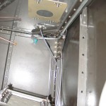
With the CNC cut panel in hand, I set to work getting it ready for installation.  This meant that all the switches and stuff I put in for fun had to come out, but I knew that was coming.  First, I drilled the holes for the RH panel rib using the stock panel as a template.  I discovered that the panel was rubbing the canopy deck on the right side (I’m guessing that the canopy decks and/or longeron heights are not 100% symmetrical), so I trimmed a bit of material off the edge to make both sides match and fit nicely.

The big piece to fabricate (it’s been awhile since I had a “make from” instruction) is the reinforcing angle which runs along the top of the panel and stiffens it.  This is just a piece of 3/4″ leg angle, but it it tedious to make because it needs a bunch of slots made in it to allow it to bend around the curve of the panel top.  While I was on that sort of a track, I also finished up the canopy seal holders which needed the same treatment.  I ended up drilling the radius holes with a #30 bit (R-1/16) on the drill press, then marking lines for the 15* slots and cutting with a hacksaw, as the angle is too long for the bandsaw.  Clamping to the bench and filing both sides, then the radius, finished it off; after that it was a relatively easy task to drill to the panel.  That particular job ended there, as I can’t seem to locate my #40 countersink cutter.  There’s also two small angles that run vertically at the outboard edges of the panel, so those were made and drilled too.

With the panel clecoed in place, I set to work on the vent brackets.  I’m going off-plans here, since I am installing the SteinAir vents, which don’t mount with screws like Van’s vents do.  I decided to cut a couple pieces from the stock panel blank, keeping the bottom flange, and nest the radii together with the vent bracket behind the panel.  A piece of angle attaches the bracket to the side skin at the four pre-drilled holes.  Easy enough in concept, but fitting it all up and drilling everything took some time.  I also added an additional screw hole to the lower part of the panel that will affix it to the vent bracket; this should provide some extra solidity to the switch row.

Pulled the panel out and deburred the work that was done, then drilled the canopy seal holder angle to the subpanel.  I’ll need to do a priming/painting job sometime soon here so things can be assembled.

One more project…installation of the throttle quadrant.  I’ve mapped this out in my head, so it wasn’t that big of a deal, and it was fun to see it in the plane.  I cut a couple pieces of angle to run from the panel to the subpanel, providing a place to attach the TQ–here I’m using hardware store angle as was suggested by someone on the forums, since it doesn’t have a radius on the inside of the vertex, which allows the TQ to seat firmly inside.  Another piece cut from the stock panel blank provides extra length at the subpanel to compensate for the added length of the panel.  Securing the angle pieces to that bracket with bolts will give a handy place to use adel clamps for the purge & cabin heat cables that will go to the outsides of the quadrant.  The front of the angles are secured directly to the bottom flange of the panel.  I was going to mount the quadrant on center, but sitting in the plane fooling with various positions, I ended up cheating it just a bit to the right, so the flap switch would be easy/comfortable to reach with my hand on the throttle lever.  It’s only 1/2″ or so off center, so not very noticeable and not encroaching too much on passenger leg room.

Looks like I might be forced to clean the shop tomorrow so I can find that countersink bit…

Hours: 7.3 | Posted in Cabin & Interior | Comments Off

19th February 2011

Panel arrives

The CNC-cut panel arrived on Thursday so I’ve done a couple hours of fooling around, putting in switches and indicators to play with and show off…I mean, to check that all the holes are correctly sized.  I did find that when I drew the pots for the light dimmers, I mis-measured and put the alignment holes off by a couple 32-nds.  I just filed them into ovals with a tiny round file; the placards will cover it up.  Everything else–at least the pieces I have–fits well.

With the dimmer pots temporarily in the panel, it seemed like a good time to wire them up, so I soldered the cable that runs to the dimmer module to them.  Everything will come out, of course, for more panel construction, but it was easy to solder them seated in decent light.

Also ordered more random stuff from Mouser (connectors, switches I forgot to order, extra switch hardware and locking rings), McMaster (channel for the backlighting, cap screws, washers), AFS (tray & harness for the second screen prewire), plus a Garmin 18x 5Hz GPS, which will feed position info to everything onboard in phase 1 of the panel: EFIS, ELT, APRS.

Also heard from the placard engravers, and they should have shipped on Friday.  Now just waiting on avionics, which I’m hoping for in the next couple weeks…AFS said they shipped their portion of it to SteinAir on the 17th.

Hours: 2.0 | Posted in Electrical | Comments Off
14th February 2011

Panel preview

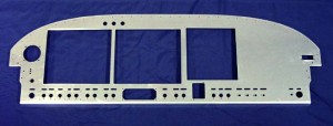
Word came today that the panel has been CNC cut and shipped…even a picture:

Looks good…should arrive later this week; more details when it does.  Still no word from the placard engravers.

Posted in Electrical | Comments Off
12th February 2011

The small stuff

Not alot of visible progress for the hours today, just working on a number of small things.

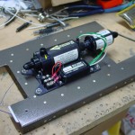
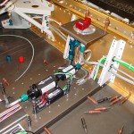
  • Assembled a .040″ restrictor orifice into a -4 straight nipple fitting, and installed into the #3 cylinder for pickup of manifold pressure.  The #10 sized orifice from McMaster-Carr (2943T887) works nicely in a -4 fitting size, just requiring the fitting to be tapped.  After tapping the fitting, I installed the orifice with high-temp threadlocker.  I also tapped the orifice from the hose side, rather than the cylinder side, so that if it were to somehow work loose, it could not travel into the engine, but into the hose.

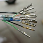
  • Finished installing the wing wiring connectors by terminating the wires on the left wing.
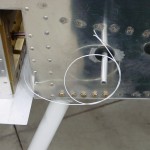
  • Reinstalled the fuel vent line tubing that passes through the fuselage sides; torqued the fittings.  Cut the vent lines to proper length.
  • Smoothed and flared the ends of the fuel pickup and vent tubes that protrude from the fuselage.

  • Riveted the doubler plate for the fuel pump to the tunnel cover.  Fabricated a pair of stiffener angles for the same cover, to beef up the sides of the assembly and reduce vibration.  Affixed the pump to the cover plate, and test fit it in the fuselage; tweaked a couple fuel line bends to get the selector-pump-firewall plumbing aligned.  Cut and terminated the fuel pump wires.

  • Put some temporary zipties on the tubing in the tunnel to hold things in place for now.
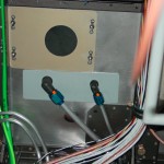
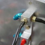
  • Removed the firewall passthru fittings to fabricate and install a doubler on the inside of the firewall.  I had used the thick aluminim spacer/washers that Van’s sends, but there was too much flex in the FW still for my taste; this beefed it up nicely.  Reinstalled fittings with doubler aft and spacers forward, and torqued fuel & purge return lines at the firewall.

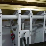
  • Installed the closure pieces for the inboard seat pan ribs, that bridge the gap which is cut to allow installation/removal of the control column.
  • Temporarily installed the roll trim assembly in order to find the correct angle for the metal tabs that bolt to the lower end of the control sticks, so I could torque the bolts on the rod ends that tie the sticks together in roll.  Also to see how the trim goes together.  Followed the plans for setting the spring lengths, but they seem as though they might be overly tensioned…need to see where others have ended up on the length.  The issue may be that the plans have you use the forward-left-most stick position to set the spring lengths, and without the elevators and ailerons attached to hit their stops, I suspect the stick travel is a fair bit more than it would be normally, which would result in stretching the springs excessively.  So, setting the spring length may end up part of the after-final-wing-mating task list.
  • Also torqued the bolt for the elevator pushrod at the control column.

I found that the Goop used on the stick grips cured well, and the grips are solid.  Also sent off what I hope will be the last of the minor revisions on the panel layout, so that should be cut sometime next week and on its way.  Hoping to have the harnesses from SteinAir sometime soon, as that’s all I’m waiting on to wrap up the airframe wiring.  Had made contact with the engravers about doing the placards for the panel, but they seem to be slow on the email (or at least haven’t replied yet), so I’m not sure the current status of that piece.

Hours: 6.8 | Posted in Center Fuselage, Electrical, Plumbing | Comments Off

6th February 2011

Wiring work

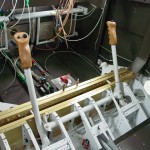
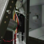
More work on wiring, essentially finishing up the stick install from yesterday by tying up wires and connecting connectors, making sure everything is neat and secure.  Also installed connectors on the feed to the flap motor and hooked it up, as well as the heated seat power lines, and the flap position sensor.  I’m not going to final-mount the position sensor yet, as I need to obtain some threaded rod and clevises to hook it up.

Vacuumed out the area under the seat pans, then decided to cut out the left panel support rib (which will be reinstalled a few inches to the right, to clear the EFIS screens).  That, of course, required another vacuuming…but the Dremel with a cutoff wheel made easy work of it, then cleaned up the cut edge with files.  Dust was mostly controlled by holding the vacuum nozzle alongside the cutting wheel.

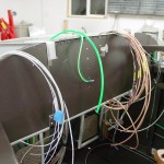
With those items finished, I moved on to the largest of the airframe connectors: the wing roots, which are 22-pin CPC’s.  (Not all 22 pins are used, though.)  The biggest thing for working with these connectors is to make a good chart of what’s hooked up to which pin, so that both sides of the connector end up the same.  I also used the same pins on left and right sides for functions that are duplicated on both sides (landing/taxi lights and nav/strobes).  I was able t0 finish both fuselage sides and the right wing before dinner.

Hours: 4.5 | Posted in Electrical | Comments Off
5th February 2011

Plumbing and wiring

Working on several areas today:

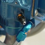
  • Installed 1/8″ NPT to barb fitting nipples in the transducer manifold for the manifold pressure line; one will feed MP to the P-Mags, the other to the sensor for the engine monitor screen.
  • Fit and temporary-installed silicone tubing from the manifold to the P-mags, and a stub for the MP sensor when it arrives.
  • Measured for fuel hoses and pressure sensor lines (fuel, oil, MP) with a piece of tubing.  I should now have the list of most of what I need to order, except for the oil cooler hoses, which I won’t be able to measure until baffles and cooler are installed.
  • Ran wire from the panel to the wing roots, forward of the main spar, for the fuel level sensors; wires I forgot in the earlier wiring work to those locations.
  • Pulled wires to the FWF electrical area, for master contactor, starter engage, and starter engaged annunciator.  Terminated and landed the contactor ends, and verified proper operation of the contactors.  Secured the wires, at least for now.  These should eventually get high-temp tie-wraps.
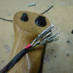
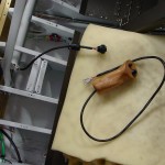
  • Wired the connectors on the stick grips, and glued the grips on with Goop.  I’ll have to see how it cures in a few days, whether it’s too soft for this or not.  I believe it will be removable with enough force, which would be a positive thing if I ever wanted to change grip function (add a switch, for example) or if a wire needed to be repaired.  But, I want it to feel solid, and the grip not to move or flex under normal use.
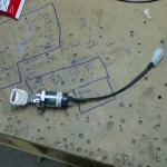
  • Put connectors on the master keyswitch and the aux PTT switches.  These connectors aren’t strictly necessary, as the wires could be soldered to them inside the plane, but soldering is a much more pleasant experience when not carried out upside down; I also want to be able to remove the panel without the need to unsolder things, which means a connector on the master switch, since it installs from the front of the panel (unlike the toggles, which install from the back with nuts on the front side.)  Installed the aux PTT switches, and glued a tie-wrap base to the underside of the forward canopy decks to secure the PTT wires and static line.

Hours: 7.3 | Posted in Cabin & Interior, Electrical, Plumbing | Comments Off