30th April 2011

Cowling strips

Spent a bit of time messing with the cable throws on the throttle and mixture, then moved on to the beginning of the cowling tasks. For some reason, I’d been dreading making up these camloc strips, but it wasn’t that bad. I took off the top skin and used the forward edge of it as a template to get the necessary curve. I’ll have three pieces: one pretty straight section in the top center, then one additional section on each side to run to the bottom of the top cowl. The pieces have a hockey-stick shape when laid flat, but they fit nicely to the curve of the firewall, and the angle is correct for the slanted portion at the top. Turned out well, so I drilled the side segments in place. Ran out of time to drill the top center piece, but it’s ready. Worked on measuring off the layout for the camlocs, to see where the divisions of the strips could be without interfering, and marked the strips for cutting.  At the spacing I ended up with (3 14/32″), I’ll have 16 fasteners on the top cowl.

Hours: 2.3 | Posted in Cowling & Baffles | Comments Off

28th April 2011

Exhausted

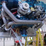
The Vetterman crossover exhaust (with mufflers) arrived this morning.  After unpacking, I took it out to test-fit.  The flanges fit right up, and it looks like there will be sufficient clearance from all the hoses, wires, and such.  It’s not really bolted on yet, just held in place with a few bolts.  Not sure if it’s best to fit the cowling with or without it on, and it will need to come off to be drilled for the EGT probes, anyway.

Messed around with the control cables for the throttle and mixture, temporarily attaching them to the fuel servo.  There is a long distance from the end of the cable to the fixture nuts, so I’ll need to move both of the control brackets one more hole aft before creating the brackets to hold the cables.  Drilled out the mounting hole for the purge cable and fit that to the panel; that one still needs to have the FW eyeball installed (as does the alternate air cable, when that’s ready…)

Pulled out the cowling again and started looking at how to fit it.  I have a 2×2 sheet of .063, which will probably make the camloc strips, but it’ll need to be done in 3 pieces as the dimension to span is around 53″.

The verdict on the AFS/VP-X amps & volts is that it’s not currently supported to source the gage reading from the VP-X datastream.  Hopefully they’ll consider adding this in a future software update; it seems a bit silly to have a current shunt (and associated cables and connectors) when the data is already there.  For now, I disabled display of the ammeter.

Hours: 1.5 | Posted in Engine | Comments Off

27th April 2011

It must be the weather

It was interesting to me that two things appeared in the last couple days that found me where I’m at: an article in EAA’s homebuilding e-newsletter, and parts of a thread on VAF, both around with what the article named “Project Paralysis.”  It must be the weather–for most of the month, it’s been gray, gloomy, raining/snowing, and cold (running 10+ degrees below average; we had snow yesterday for a bit).  March was exciting, and I put in far more hours than expected (nearly 80), but April has been a downer.  Only 25 hours, and the motivation to head to the shop in the evenings hasn’t really been there.  Work is heading into the busy spring season, which will last the next 5+ weeks, but I don’t think it carries the sole blame for the lack of energy.  Must be the weather…here’s hoping the snow stops soon.  On the bright side, I’ve spent some good time with Allison talking/dreaming/scheming about plans for the summer and beyond.

This week, though, has been looking up.  Lots of boxes arriving, the UPS man has been here every morning.  Engine hoses, control cables, and my AFS screen are here, and the Vetterman exhaust should be in tomorrow.  I’ve been reading up on fitting the cowl (among others, a good thread by Brantel on fitting the pink cowl, and a new one on baffles, plus DanH’s highly informative and well-illustrated fiberglass tips), which seems like a logical next step.  I need to pick up or dig up some PVC pipe to use as a stand-in for the prop spacer, and fit the camloc strips first.

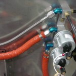
The task list for tonight was simple, and easy to motivate with new and exciting parts: test-fit the hoses, and fire up the EFIS.  All the engine hoses seem to fit well (though the oil cooler is not yet installed, so those can’t be fit yet).  I got these from Tom at TS Flightlines, who was easy to work with and fast getting them out.

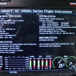
The EFIS screen (AFS 4500-EE), having already wired all the harnesses during the panel install, slid right into the tray and powered up.  Spent some time going through the menus, configuring serial ports and such.  Two oddities I noticed (1. the master warn light never illuminated when it should, but did when the screen was powered off, and 2. the screen always powered on when the master was turned on, even though the avionics bus wasn’t on), turned out to be related, and a simple fix: I had inadvertantly inserted the pin for the master warn light into the wrong hole, which caused it to be hooked up to the backup power input.  It was getting power on that backup input when the master went on (since the annunciator power is always on), and booting up (and illuminating the light).  Once primary power was applied, it stopped using that backup input, and the light went out.  Moving it to the correct pin solved both problems.

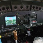
Allison came out and I put her seat in, and we sat in the plane looking at the panel.  Tested that the audio out of the AFS works, and it talks to everything hooked to it: VP-X control, transponder gets altitude, a finger in the CO detector pops up a readout of O2 saturation and heartrate, and it sees data from the GPS.  I posted a message on the AFS forum about the volt and amps gages…I had been under the impression they would take their readings from the VP-X datafeed, but that doesn’t seem to be the case, or at least I can’t find it in the menus.  The voltmeter is using the internal sensor of the AFS (not a big deal, it matches the VP-X within 0.1 volt, but of course reads 0 when the avionics master is off), and the ammeter just reads 0, since I didn’t install the shunt (since I thought it would come from the VP-X).  Both values are displayed on the VP status page, but it would be nice to have them as gages in the display, and be able to alert on them.

Hours: 2.0 | Posted in Electrical, Engine | Comments Off

23rd April 2011

Contortionist

Did a couple more odds and ends that needed doing, including some fun contortions to work in the baggage and tailcone areas:

  • Installed the DB-9 connector for the autopilot pitch servo
  • Installed new nutserts to secure the seat heater relays in their new positions
  • Torque seal on the fuel flow transducer bolts
  • Installed nutplates for the aux alternator relay and capacitor
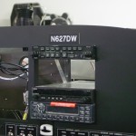
  • Placed the N-number placard on the panel

Also refit the canopy and forward top skin in order to look at a few things up there:

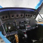
  • Attached wire to and nstalled the strip of LED’s that will be the panel floodlights.  Temporarily connected to the switch to test; still need to run those wires for real and put a connector behind the panel.
  • Checked again for clearance between the outer top corner of the EFIS and the panel reinforcement; looks like it should be fine, as planned.
  • Checked for catching of the canopy skin when opening; looks ok after filing off a bit more from the forward edge.
  • Found where the canopy frame is rubbing on the side seal support angles (which weren’t yet installed when the canopy was previously fit).  Those will need to be filed down for clearance.

Hours: 4.3 | Posted in Canopy & Frame, Electrical | 1 Comment

16th April 2011

Putzing around

Spent most of the shop time tonight just standing, staring at the project, trying to divine the way forward.  Did manage to accomplish a few things:

Installed the fittings on the fuel flow sensor, and installed the fuel flow sensor to the mounting plate with 1/4″ bolts and torqued.  (Note to self: put torque seal on fittings)

Located a spot to mount the relay and capacitor for the SD-8 backup alternator…of course, the adel clamp necessary to mount the cap appears to be a -22, which is the one even size I don’t have on hand.

Moved the seat heater relays forward in the tunnel, and rerouted the wiring harnesses.  This change was necessary because I discovered after putting the seat cushions in, that the wire from the seat bottom wasn’t long enough to allow for the movement that happens when the seatback is tipped forward (such as loading baggage), without unplugging it.  So, I brought the relays forward as far as practicable, which let more wire stick out of the tunnel.  I still need to re-do the mounting of the relays; they’re ziptied to the tie base that was previously holding the cables, but I’m not satisfied with that, since this is in close proximity to a flight control (elevator pushrod).  I’ll probably put in another rivnut as I did in the earlier location–could also pop-rivet them down, but relays are mechanical and will fail, requiring removal for service.

Hours: 2.1 | Posted in Electrical | Comments Off

12th April 2011

Oil cooler test

I wanted to get the order put in for all the FWF hoses at once, and to do so, I needed to identify what hoses were needed for the oil cooler hookup.  This, in turn, required test-fitting the aft left portion of the engine baffles.  The good news is that I was able to figure out what hose lengths would work, and I’ve sent that off to the guy who’ll be making the hoses.  I also determined that the hose routing should work with the wire runs and such I’ve already mounted.  I did move one adel clamp to provide some additional clearance at the lower corner of the cooler.

Also received the package from Van’s today with the AeroLED lights — these things are bright!

Hours: 1.5 | Posted in Engine | Comments Off

11th April 2011

APRS Tracker

My APRS transmitter from Byonics arrived today (along with an oil cooler and spark plugs from Spruce), so I thought that would be a simple and satisfying installation.  First, I opened up the tracker and wired a short piece of 22-3 to the internal LED, bringing it out through a small hole in the case.  A 3-pin Molex went on the end–this is to drive a bicolor LED like the one built into the tracker, but external, since I will have the tracker mounted behind the baggage bulkhead.  Having installed a TinyTrak in my car, I know it’s handy to have the status lights to see what the tracker is doing.  With the external LED plug wired, I closed the case back up and proceeded with the installation on the plane.

I put a pair of small holes in the baggage bulkhead, far enough to the side that they won’t interfere with the corrugated wall panel.  The top hole received the bicolor LED; it indicates green for GPS status (flashing means it’s receiving data, solid indicates a valid fix), and red to indicate it is transmitting a position packet.  The lower hole is occupied by a 3.5mm TRS jack, similar to the ones I’ve used in several other places for RS-232 service ports.  This one is a bit different, since the other (Pmags and ADS-B) are dedicated serial ports on the devices, whereas the tracker also receives its GPS signal via this port.  So, a normalling jack is used here — when there is no plug inserted, the GPS signal is fed to the tracker.  Inserting a plug breaks the GPS connection, and connects the tracker’s input and output to the computer.

I could have put the LED on the panel, but a) it’s not at all a critical item, b) the flashing light could be distracting, especially at night, c) that would require another wire through the spar, and d) it’s still readily visible by looking over my shoulder.  Both the LED and the port are easily accessible for servicing the tracker and checking it’s operation, while being completely out of the way.

Wired the tracker to power, too, and enabled that pin on the VP-X.  Terminated the coax from the NMO mount with an SMA connector, hooked that up and flipped the switch.  The tracker booted right up, so I powered the GPS and got a solid green light.  Good to go.  The service port is functional, and I programmed the tracker config and grabbed my handheld scanner to verify that it is transmitting.  None of the packets hit the internet, which doesn’t surprise me at all since it’s on the bottom of the fuselage (which makes sense in the air), and inside the shop.

Hours: 2.5 | Posted in Electrical | Comments Off

10th April 2011

Random pieces

Long week with no work on the project; the busy season has begun at the office.  Some positive news on the financial picture front this week though, so I at least ordered a bunch of pieces that I’ve been holding off on, for upcoming installation (lights, exhaust, APRS stuff, ELT, oil cooler, etc).

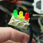
Got a few things done and half-done today; starting off with the wiring for the pitot indicator.  I bought my Gretz pitot secondhand, and it didn’t include the indicator board, since the previous owner had installed it in his plane.  No problem, it’s just a few LED’s with appropriate resistors, but I hadn’t yet taken the time to measure the voltage, find the right resistors, and build the board.  I used a chunk from a leftover piece of prototyping board, trimmed to fit the necessary components.  I also put a 4-pin Molex connector on it, for ease of connection (the soldering could happen on the bench, rather than in the plane) and service.  A matching connector on the wire behind the panel, and we’re in business.  I connected up the pitot for testing, and rolled the wing cart over to plug into the fuselage.  Power on, and everything looks good: the lights indicate as they should, the heater cycles, and the tube tip gets hot.  While I had the left wing hooked up, I checked the function of the leading edge light and made some minor programming changes in the VP-X (renaming some pins).
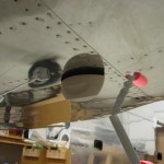
Installed a standard NMO mount and the Antenex Phantom Elite antenna I ordered, which will be for the APRS installation.  I also ordered the new MicroTrak RTG FA from Byonics, which should arrive next week.  The antenna is mounted halfway between the comm antennas and the transponder antenna.  I could have mounted it aft of the transponder antenna instead, but since the VOR/Loc antenna location is at the tail end, I thought it better to keep the APRS more distant, since the APRS and Nav signals are on nearby frequencies, while the transponder is removed by several hundred MHz.
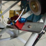
Thanks to some photos helpfully posted on a VAF thread, I decided to figure out the installation of the fuel flow sensor.  I fabricated a mounting plate from some scrap .125 bar stock, which attaches to a pair of engine mount tubes via Adel clamps.  The sensor mounts to the plate using it’s own 1/4″ mounting holes, for which I of course don’t have the correct length bolt (AN4-17A).  I also need to order the steel nipples for the in and out of the sensor; the sensor ports are 1/4″ NPT, rather than the 1/8″ commonly associated with the -4 fluid lines, so that will require the “-4-4″ nipple, which is 1/4″ NPT to -4 flare.  I cut off the spade terminals on the sensor wires and fit a 3-pin Molex instead, then ran the harness wires to the sensor location and connected the two.  I also installed Adel clamps to strain-relief the wires both at the sensor and at the connector.  Since the mounting plate floats in space between the two engine mount tubes, it’ll be possible to wrap the entire assembly in a piece of firesleeve.
With the FF sensor located, I set about measuring for fuel lines, and re-checked all the ones I’d measured previously.  I have a list of 8 hoses that need to be made up now.  There are two more yet to be measured, for the oil cooler lines, which won’t be evident until the oil cooler arrives and is at least mocked up in place.  Plus, the brake lines, but at least those are already known lengths.  The steel oil cooler fittings will also need to be ordered.

Moving back inside, I experimented with various locations for the pitot/static manifolds.  Fabricated a bracket to mount both, one atop the other, and mounted it to the subpanel.  I need to pick up some longer #6 screws to mount the manifolds to the bracket, though.  Trimmed and inserted the pitot and static lines, and a pair of jumpers for EFIS 1.
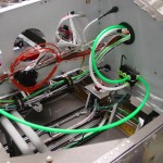
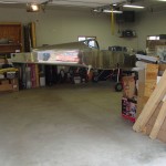
Also spent time cleaning the shop, tossing/recycling the large pile of debris that had collected under the plane.  Storm season is here, and I need to get at least one vehicle inside when weather threatens (as it is this weekend).  I figured out that I can move the fuselage 90 degrees to the right and Allison’s car will tuck nicely under the tail.
Passed 1300 hours in this session.
Hours: 8.2 | Posted in Electrical, Engine, Plumbing | Comments Off

2nd April 2011

Forward cabin loose ends

More wrapup of loose ends in the cabin area, mostly dealing with the last of the electrical:

  • Installed the DB-37 connector shell and hood for the ADS-B, and tied up that bundle.
  • Installed the hood on the ARINC module connector.
  • Soldered the 3.5mm jack on the ADS-B maintenance port connector, enlarged a tooling hole in the subpanel, and installed the jack there.
  • Fabricated engine ground cables and installed between the firewall ground buss and the engine case.
  • Measured for throttle and mixture control cables.
  • Cut and installed the ducting between the vent scoops and the panel vents.  (Need to get some screen mesh to put on the vent scoop end to prevent ingress of bugs.)
  • Removed the parking brake cable from its mount, so that the mount could be removed and painted.  Realized that the ball bearing fell out of the cable mechanism; spent some time searching for it in vain.  (Hint to similarly troubled souls: ACS sells replacement balls for $2 apiece; a bag of 50 is under $5 at McMaster, and then you can lose it 49 more times.)
  • Swapped out all the screws on DB connectors for thumbscrews…much easier to work with, especially upside down under the panel.
  • Installed a snap bushing in the left subpanel rib for the pitot and AOA lines to pass through.  Ran those lines up the left vertical FW stiffener and tied in place.
  • Tidied and tied up the bundles of wire in the tunnel.
  • Cut pieces of vinyl tubing to slip over the tubing in the tunnel for anti-chafing at tiedown points.  With much contortion, tied up the fuel and brake lines in the tunnel.  Still a couple to do, and one tiewrap base where the glue is obstructing the hole; it may be possible to open it up with some safety wire.

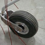
The day’s other task was attempting a redo of the nosewheel bearing.  When I installed the wheel before hanging the engine, I noted that the rotation was quite stiff.  I have the Matco axle which was supposedly designed in part to alleviate that problem.  It’s very stiff…one theory was that I didn’t manage to properly grease the bearings (they are tricky to hand-pack with the molded rubber seal).  So I bought a bearing packer cup, which did a fine job of packing it; grease squeezes out under the seal.  Re-installed, and no change.  If I tighten down the ring on the axle that’s supposed to set the preload (the instructions say to tighten it until the bearing face does not rotate with the wheel), the wheel requires what seems to me to be a lot of force to rotate.  Given the discussion around the nosewheel issues, this doesn’t seem right.  The bearing cones feel fine on inspection, too.  Anyone out there with experience installing the Matco axle that can confirm or point out where I went wrong?  For now, put it back together, knowing at least that it is well-lubricated.

Hours: 5.7 | Posted in Electrical, Gear & Fairings | Comments Off