28th June 2012

That’s how we roll

The replacement nav/strobe assembly arrived, along with the replacement wingtip lens.  My hangarmate fixed my up with an engine hoist and sling for raising the nose to work on the nosegear.  So, time for a night at the hangar.

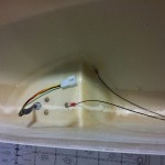
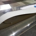
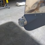
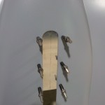
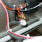
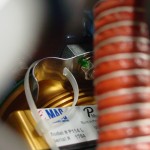
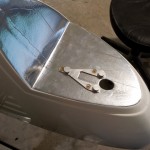
Trimmed the leads on the new nav/strobe, and crimped on Molex pins.  Tested it out for awhile, and it stays in sync with the others, so — problem solved.  Removed the old unit from the wingtip and installed the new one.  The faulty one will be on its way back to AeroLEDs tomorrow morning for an autopsy.  While I had it off, I grabbed a photo of the mounting bracket installed.

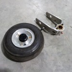
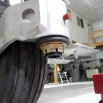
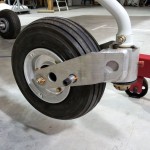
Easily raised the nose with a sling around the prop spacer, hooked to the engine hoist.  I removed and disassembled the nosewheel and fork, cleaned the axle shaft/bearing seal mating surfaces, and installed the axle according to the directions (tighten the ring until the bearings don’t rotate with the wheel), then tightened the screw on the preload-setting ring.  Set that aside for a bit, while I attended to the fork assembly.

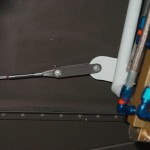
Cleaned & greased the bushings in the fork, along with the spindle.  Slid the fork on and installed the washer stack and big nut, then tightened it down with the giant (3/4″ drive) socket/ratchet, until I had the desired figure on the fish scale.  My cheapo fish scale I bought isn’t perhaps the pinnacle of professional measuring devices, but it got the job done.  On the advice of those who have gone before, I set the breakout force high (26lbs), so it has room to drop as the parts wear in during initial use.  Once I had that set, I drilled the 1/8″ hole across the spindle, removed the nut to deburr, and reinstalled the whole stackup with cotter pin.

Reinstalled the nosewheel to the fork, torqued and marked everything, and we’re done.


Hours: 2.2 | Posted in Electrical, Endgame, Gear & Fairings | Comments Off

24th June 2012

More tips

Yup, another day working on the wingtips.  I’m not at all convinced that this hinge method is easier, as some said, than doing all the nutplates.  I’m reserving judgement on the outcome until I see it all done, though.  One upside that I do see is the ability to get the tips “done for now,” and then with relative ease, remove them for additional fiberglass finishing later on.  That’s a good thing.

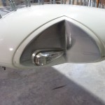
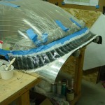
Drilled, mounted, and wired the AeroLEDS wingtip lights.  I lined the wingtip cutouts with strips of aluminum tape to give it a pseudo-mirrored look; the glasswork underneath isn’t perfectly smooth, though, so there are some visible seams and lumps.  I expect this will be somewhat temporary, and will be redone later with tape over smoother glass, or perhaps a thin sheet of mirrored plexi.


Discovered that the right (green) light assembly seems to have a problem with the strobe sync; while the left and tail strobes flash together, the right one drifts in and out of sync.  Swapping left & right, the problem stays with the unit, which indicates a fault with the unit, and not with the wiring.  (Update 6/25: AeroLEDS agrees it sounds like an internal problem, and is sending an advance replacement for the suspected defective one.  Defects happen, that’s expected, and it’s good to see a company handle it this way.)

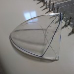
Attempted to start fitting the tip lenses, and promptly put a big crack in the right one with the bandsaw.  Dang.  New lens on order, and we’ll start over with that.

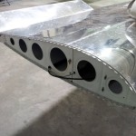
On to the tip hinges…did all the necessary deburring and countersinking (yawn), and was able to get the hinges riveted to the wings and wingtips, by staying at the airport way too late for a “school night.”


Hours: 9.1 | Posted in Electrical, Endgame, Wingtips | Comments Off

17th June 2012

Small stuff

Not a ton of progress today, because I switched vehicles with Allison and in doing so, forgot to load up the stuff I needed to get started on either of the two major projects I was considering.  So instead, I worked on some smaller stuff.

I’m not using two of the three switched aux inputs to EFIS 1, and I want to have some way of marking data in the log files during flight test (for use in calculating performance or looking at some specific occurrence in more detail).  I checked the logs files and it turns out that the state of the inputs is logged.  So, I decided I would install a simple toggle switch that I could flip to mark data, which I could find later by looking at the logged state of the input.

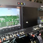
I have a blank panel I made to cover the open mounting tray for EFIS 2, so I drilled a 1/4″ hole in it and mounted a miniature toggle.  Opened up the D-sub connector on the EFIS and swapped the pin in (the other side of the switch is connected to ground).  I programmed the EFIS to display “Data Marker” on the screen when the switch is on.  It’s not super pretty, or match the rest of the panel, but it is not intended to be a permanent install — just for gathering test data.  I’ll remove it completely when I install the second EFIS someday…unless it proves to be amazingly useful for some reason beyond my expectations.

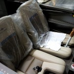
Decided for selfish reasons to do some work on the interior — secured the seat pans with several screws each (they’ll be removed for inspection again, so no reason to put them all in…it will be nice to have a seat, though, to do the engine runs).  Pulled out the seat cushions and installed the velcro patches on the seatpans.  I need to find the stick boots…

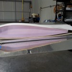
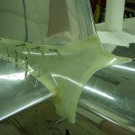
The rest of the session was back on the wings.  I made a pair of foam ribs that match the airfoil shape, to use inside the wingtips.  Also looked at the wingtips to see how they would need to be trimmed, and swapped around some pieces of hinge in preparation for mounting the tips.

Moving to the inboard end of the wings, I deburred & dimpled the screw holes in the wing root fairings, and mounted them in place.  I marked a line 5/16″ or so from the side of the fuselage, down the entire length of the fairing strip, then removed and trimmed to the line.  Filed the edges of both strips, and brought them home to finish the edges on the scotchbrite wheel.

Milestone: not only is it our 6th wedding anniversary today, but I also crossed 1800 hours logged on the project.  That’s an average of 300 hours per year…thank you, dear, for tolerating & supporting this crazy idea of mine!  We’ll go flying soon.

Hours: 5.1 | Posted in Cabin & Interior, Electrical, Endgame, Wing & Tail Joins | Comments Off

28th May 2012

Loose ends

Amid the craziness of this week and next, I made it out to the hangar for a couple hours tonight.  Worked on a couple of punch-list items.  First, I’d brought the electrical toolbox, so I was able to extract the old sockets from the taillight molex shell, and insert the new ones.  Then, install the taillight to the rudder and test both nav & strobe functions.

Safety-wired the pitch trim hingepin in place.

Dimpled the screw holes on the bottom fuselage skin, that overlap onto the wing; these would be impossible to dimple after the wings are installed.

Measured for and fabricated a closure plate for the forward part of the nosegear slot in the bottom cowling.  I forgot to bring any scotchbrite to the hangar though, so didn’t get it primed or nutplates attached, though all the drilling/deburring/countersinking is complete.

Hours: 2.2 | Posted in Cowling & Baffles, Electrical, Endgame, Wing & Tail Joins | Comments Off

26th February 2012

Filling (&) leaks

Mixed up some Super-Fil and worked it into the remaining pinholes on all the fiberglass parts that were sprayed yesterday.  Next will be sand the filler & spray another coat.

Pulled the top skin off and moved a couple pins on the ADS-B connector, since newer versions of the box have a slightly different pinout.

With the top skin off, found that a few of the elbow fittings on the brake cylinders were leaking fluid.  Removed the hoses and turned them in one more rotation, which, at least initially, seems to have cleared up the slight leaks.  Re-bled the brake system with fluid, and in the process managed to snap the nipple off one of the bleeder screws.  Dangit — at least it was only the nipple, so the brake system is closed, and I just need to order another bleeder screw.

Reconnected the oil temp sensor wire, which had been removed in a previous session to install an oil line.

Hooked up the new serial converter and it works; checked communication with the Pmags, and verified the configuration in the APRS tracker.

Hours: 6.5 | Posted in Canopy & Frame, Electrical, Plumbing, Wing & Tail Joins | Comments Off

14th February 2012

Lay on, sand off

More fun with cowling to start the day: added some glass to a spot in the nose of the upper cowling that was thinned out by sanding, and laid up a couple plies at the sides of the oil door (+ peel ply).  Took the extra epoxy and squeegeed it on the inside of the top cowl.

Taking a break from fiberglass work, I filled the brake system with fluid.  This was pretty easy with the use of the brake bleeder tank I picked up from ATS, which came with the correct bleeder fitting for the calipers.  I filled up the tank with fluid, attached a NPT-to-hose-barb fitting to the brake reservoir in place of the cap, with a clear nylon tube to the empty fluid canister, and pumped away.  Once a stream of uninterrupted fluid had flowed out of the reservoir, I switched sides and repeated.  No leaks apparent, but I still need to climb in and test the system under pedal pressure, as well as check the operation of the parking brake.

Back to work: spent considerable time sanding down the fillet of Sika at the canopy base.  I decided to do a layup of glass here, for a number of reasons.  To enable that, I pared down the Sika fillet, exposing some plexi above it, and some aluminum below it.  Scuffed everything up well, and laid out edge lines with electrical tape.  I cut a ply of “Rutan Bid” glass cloth, and a ply of a cloth with a tighter, denser weave to place on top of that; both were curves cut on a bias, for a smooth fairing with no ply overlaps.  Mixed a batch of epoxy with added black colorant, and laid up both plies of glass, plus a layer of dacron peel ply.  Today was the first I’ve used the peel ply, so we’ll see tomorrow if I did it right.

One more little item on the list, plugged into the VP-X and updated it to the latest firmware version.  The cheap USB to RS-232 converter I bought for $9 is junk and won’t install on my computer, so I haven’t been able to service the APRS unit.  I’ll borrow the one from work that I was using before, and find a better one to get for the shop.

Also looked at the fit of the Crow crotch straps, which look like they’ll fit into the brackets without trouble.

Hours: 9.5 | Posted in Cowling & Baffles, Electrical, Gear & Fairings | Comments Off

29th January 2012

Pop rivets & dust

Allison joined me in the shop for a bit to finish removing the tape gunk from the empennage fiberglassing adventure.  While she worked on that, I sanded the micro and shaped the edges of the emp fairing.  After fitting it back onto the plane, I’m pretty happy with the fit.  Now, I’m going to use this (and the emp tips) as a learning canvas for fiberglass finishing.  I have a box of PPG stuff here that I’m planning to use, which I chose because it seemed to be the most well-documented on the forums and build logs.

I also drilled the HS tips to #30, dimpled the skin, and countersunk the fiberglass.  These are ready for finishing, then attaching.  The goal with the fiberglass stuff is to get it to an acceptable level of finish and wearing a protective coating.  If it needs to be dealt with further, I can revisit it before paint (or let the pros make it shine as part of the pain process).

With the fiberglass dust (ack) cleaned off the workbench, I pulled the clecoes from the baffle airseal strips and installed the large-head pop rivets that hold it in place.

Finally, I installed the latest version of the EFIS software from AFS.  The problem where the screen blinks durin initialization when displaying the VP-X status page has not been fixed.  I pulled the config files to load into the computer and update some things.  (Hint: Linux works better than Windows for editing these files, as the line breaks display correctly…no surprise, since the AFS box runs Linux internally…)

I’ve also been working on the paperwork side, having built an InDesign project and templates for the POH, and compiling the “best of” from several existing POH’s that others have shared on their websites.  There’s lots of specific information to research and fill in, and plenty of stuff yet to write.  Being a layout nerd and a perfectionist, it’s possible to pour hours into this part, too.

Hours: 4.5 | Posted in Cowling & Baffles, Electrical, Wing & Tail Joins | Comments Off

27th December 2011

Somewhere, under all the dust

Happy Holidays — Christmas Eve is the anniversary date of the arrival of the empennage kit, so this marks the beginning of year 6 of the project.  I really hope to get this plane flying this year, though enough plans have been laid and lost that I won’t bank on it at this point.  The biggest remaining hurdles are all the fiberglass work, final assembly, and the “tax kit” (yes–thank you Minnesota–I will be required to pay over $6k in various taxes and fees before I’m allowed to fly it, and then a significant ongoing annual tax, as well…)

With Christmas as the associated family travel receding into the distance, the holiday schedule at work lined up to give us two 4-day weekends in a row.  I, like many others, decided to cash in a bit of stored-up PTO to have a 9-day mini-”vacation” from the office, before heading back to build out another recording studio in January, along with new student training and a bunch of deferred maintenance items.  And, I’m putting off the non-work work that I need to do a bit longer, in order to log a couple hours on the airplane project.

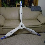
Today’s task was to find the thing under the pile of hay, dust, and remodeling debris that has accumulated in the shop since I last touched it over three months ago in September.  Several hours later, the shop was clean again, and most of the tools found and returned to their home.  A new storage stack was built out of cabinets removed from the kitchen, and more things stored away in the attic.  With the floor swept, I was able to move the plane out where I could walk around it, and, under the dust (it’ll need a good cleaning for sure), it seems to be as I left it — in need of a propeller (which arrived just before Christmas, and the spacer kit should be here next week), some loose ends around the engine, and alot of fiberglass work, plus some finishing touches on the canopy…and the rest of a two-page punch list.  Time to get started.
I finished the last task I’d started three months ago: heat-shrinking a piece of tube around a copper buss bar to connect the AFS amp shunt to the alternator fuse.  Installed that and the fuse, and put the charger on the battery to top off any charge it lost while sitting (the charger indicated very little had been lost).  I decided to install the AFS amp shunt after seeing that the VP-X amperage reading was not displayed in the bargraph metering as I thought it would, nor is there any monitoring/alarming on the amp value reported from the VP-X.  Tp be clear, you can see the amps & volts reported by the VP-X, by calling up the VP-X page, but not in the regular bargraph meters in the EFIS.  So, I put in the amp shunt, to have a reading there…but I put it in the alternator line, rather than the master buss line.  This essentially gives me the ability to monitor two different amp readings: one showing how much current is being provided by the alternator, and a second (from the VP-X) showing the total current being used by the electrical systems.  Simple math then gives the current being provided by the battery (or consumed in the manner of charging), and having both available should allow for easy diagnosis of a failing alternator and/or battery.

Pulled out the FAB and started looking at how I want to do the alternate air door…this is on the priority list, since I want to install the eyeball for the control cable before I rivet on the top skin, as drilling those holes will be easier without that in the way.  I think I will build a sliding door modeled after those I’ve seen on VAF, as there are numerous reports of the swivel door in the plans failing, when the pivot eye breaks off.  Also need to find a place to mount the control cable — probably under the parking brake handle, or perhaps on the lower left subpanel, depending on how ugly of a reach it is to access it from the pilot’s seat.

(this log entry has an inflated number of hours, as I believe there were one, possibly two, work sessions that never made it into the log, wherein the amp shunt was installed and a doubler plate fashioned for it’s mounting, the rudder pedal links installed — probably among other unknown things that have been lost from my mind over time.)
Hours: 4.0 | Posted in Electrical, Engine | Comments Off

17th September 2011

Look ma, no holes

Quite awhile today spent installing the current shunt on the alternator line — fabricated a doubler plate, drilled the mounting holes and rivet holes, installed nutplates, dimpled/countersunk, riveted in place, and located screws sufficiently long to attach it.  The location I chose (right next to the alt fuse) allowed the existing wire to be used without retermination, but I do need to buy another strip of copper bussbar to connect the shunt to the fuse.  Re-tied the wire bundles where I added the wires from the shunt to the EFIS.

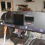
With the shunt in, I turned attention to fabricating coverplates for the rest of the gaping holes in my panel — EFIS 2 and the IFR gps/nav/comm (which will probably be a GTN650 if that day ever comes).  Cut some panels out of .032 stock, and riveted angle to the left & right sides, primed, and painted black.  I’ve affixed them with cleco clamps for now, but my plan is to try some small binder clips from the office store, as they’re far lighter and lower-profile.  I don’t want to drill holes to attach them, since I want them to be easily removable, and don’t want to interfere with the places holes might need to be drilled to mount instrument trays later on.

With the blank plates in place on everything now, the panel is essentially complete.

Hours: 5.0 | Posted in Electrical | Comments Off

12th September 2011

File under ‘Horse, getting back on’

The best laid plans, they say…  the summer was basically a bust as far as the plans I had to work on the plane, but not all for naught, as I did get some other projects started/done, and have been doing more flying, including some in-state XC day trips.  I had hoped to take a week off work in June, and a week in August, and lay down the hours; the June week I took, and spent it doing work at home, and the August week never happened due to a cadre of projects that needed to be largely done before the school year started.  Now we’re back to the old routine: evenings & weekends when other things aren’t happening.  The last home project for the summer was to “organize” (aka “restack more neatly”) the garage/shop, in hopes of getting at least one vehicle inside for the winter.  Fall will bring more projects, but tonight, I headed out to the shop for the first time in over a month.

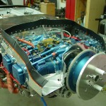
Not really having a specific place I left off, I started by looking over things and making a mental list of things that needed doing.  I decided to have a go at installing the blast tubes for the Pmags.  Dug out the 3/4″ SCAT, cut appropriate lengths, and affixed them to the flanges on the baffles with hose clamps.  The right side has the oil pressure tap elbow right there, so I secured that tube in position with a ziptie around the elbow.  The left side has nothing in the right spot for that, so I made a little holder clip that bolts to the mag hold-down stud, and has a half-circle for the tube to nest in, and a slot for a ziptie to wrap around the tube.  This worked out well, and I would have made one for the right side too, but I don’t think there is enough room to get one in there.  I also made a blast tube for the alternator, but I haven’t yet figured out how to secure it to the alternator itself, nor exactly where it should point.

I’ve decided to mount the current shunt, which I initially left out thinking the VP-X would provide the amps feed to the EFIS.  It does, but the EFIS doesn’t display it on the main screen, nor provide a way to alarm on it; it’s display-only on the VP-X page.  With no indication that this may be forthcoming, I’m opting to install the shunt, which will give me a different type of current reading anyhow; having both available may make it easier to troubleshoot certain types of electrical problems.  (The VP-X will indicate how many amps are being drawn by the electrical systems, and the shunt will indicate hoe many amps are being supplied by the alternator.)  Located and marked the mounting location, and did the inital running of the wire pair that connects the shunt to the EFIS.

Hours: 1.8 | Posted in Electrical, Engine | Comments Off