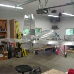
Looks like an airplane
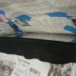
Hours: 7 | Posted in Electrical, Wing & Tail JoinsHaving picked up some different adhesives last night for the glareshield covering, the first item on today’s agenda was the finished that job. I had stupidly gotten ahead of myself and removed the inside plastic covering yesterday, in order to be able to work better down in the tight corners at the front. So, I taped up a bunch of newspaper on the inside of the canopy, to mask the bubble against any overspray. Feeling sufficiently masked, I sprayed some Super 77 on the glareshield, and a coating on the backing of the fabric, waited the appointed time, and stuck them together. I did have some troubles with the fabric sticking to the newspaper in the corners, duh…I knew there was a reason I had planned to not put adhesive on the fabric. Sigh. In the end, though, it stuck down well, and laid nicely. It appears that even with my newspaper mask, a couple areas of plexi got a light fogging of overspray, aargh. I’ve read through the VAF threads about canopy oversprays & cleaning, and sent off for some supplies from Spruce. This too shall pass, with some elbow grease.
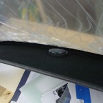
With the fabric in place, I inserted the snap bushing and GPS wire…looking good.
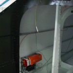
Next task was soldering the ELT connector, so I climbed into the baggage compartment again with tools & supplies. Easy enough, then I made the LED test tool specified in the manual, which lets you see if the GPS signal is being received by the ELT. It was, so I buttoned that install up; if I can remember to bring my modular crimpers home from work tomorrow, I’ll be able to put a bow on the ELT installation and cross that off the list. I also ordered the batteries for the remote units today, having failed to find them at 3 local stores that carry camera batteries.
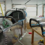
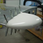
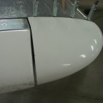
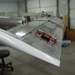
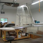
I decided that for whatever reason it was time to set the lengths of the control system pushrods, so I moved things around enough to fit the empennage. I also primed some spacers and things that needed priming, part related to the empennage attachment. Bolted on the HS and mounted the elevators. Decided to fit the HS tips, so I had to do a little bit of trimming, and cleaned up the stepped edge to a nice crisp line with files, before positioning and drilling. A couple trips in and out of the tailcone had the pushrods adjusted to get full stop-to-stop deflection of the elevators, hitting the travel stops at the elevator end rather than the control column end. I measured the travel of the elevators to verify it was within spec, and it was.
Since I had the elevators rigged up, I figured I would connect the trim servo and configure it in the VP-X and EFIS. That was a simple proposition, but I found that the pins for the up/down trim commands into the VP-X needed to be reversed opposite of what’s indicated on the load planning document (ie, 18 down, 19 up). Once the correct motor polarity was set, the buttons in the software caused the servo to move correctly (“move up” moved the tab down for nose up trim), but the stick switch was running opposite that. I tested the pins to be sure that I hadn’t reversed them accidentally — I hadn’t, the one marked up was indeed grounded when the up trim switch was pushed. Swapping the pins at the input of the VP-X allowed it to run as expected. Not sure what’s going on here, and I’ll be sure to double-check this system later to be sure it’s functioning properly, that I didn’t just have a bad brain day and set it up backwards. Once it was running right, I measured the travel of the tab to be in-spec, as well.
Finally, mounted the VS and rudder. Connected the rudder cables to the rudder horn. Looks like I’ll need the connecting links to be around 2″ long — now, where to find the steel bars that they’re made from… The rest of the empennage tips will get fitted next, I think; a little fiberglassing practice to close them out, then those surfaces can come back off for storage until final assembly.
