29th June 2010

Tail attach

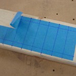
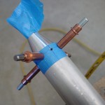
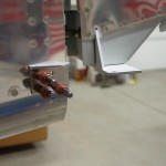
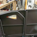
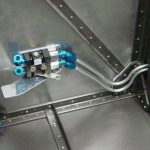
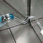
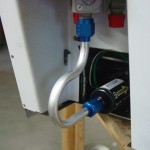
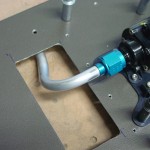
First thing on today’s agenda (well, after the dentist and barber) was rigging the elevators, which meant building the long pushrod that runs from the bellcrank to the elevator horns.  I looked at the plans and added 3/8″ to the pushrod length for fudge factor (easy to remove more, harder to put it back on…).  Cleaned up the ends and taped the fittings and rod end bearings in place, then set the total pushrod length to match the plans.  This turned out the be right one when I put it in the plane: the bellcrank was at it’s neutral spot, as were the elevators.  This is a moving parts moment, so I had to unclamp the elevators for a moment and move the bellcrank while watching the elevators move.  The pushrod was then removed and the ends marked and drilled, with the hole layout done on a piece of tape as a template.  I sloshed primer inside the tube and set it aside to dry for later riveting.

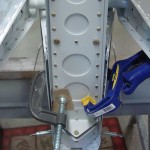
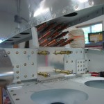
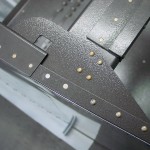
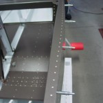
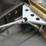
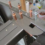
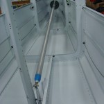
Fitting pushrod, aft end Fitting pushrod, forward end Tape marker for rivet layout Drilling pushrod

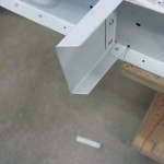
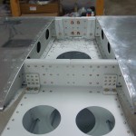
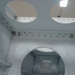
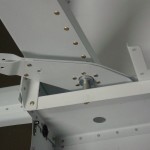
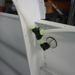
The vertical stabilizer was mounted next.  Since this uses the elevator up stop as part of its attachment, that needed to be fabricated and installed (odd that I could not find where the manual says to install this, but clearly it needs to be installed prior to fitting the VS, since it says to drill the VS to it).  Before installation, the VS front spar also needed to be trimmed at an angle to fit.  The installation required some careful, though not difficult, measuring to set the proper angles.  Clamp well, drill, bolt, repeat for the three locations where it is attached to the fuselage.  The tiedown bar differed somewhat from the manual, because I fabricated and drilled it to the aft bulkhead when building the bulkheads.  So rather than drilling the holes in the VS/bulkhead stack and then match-drilling the tiedown bar, I simply back-drilled the VS through the #30 holes in the bulkhead, then enlarged from the outside to 3/16.  This worked well, and the VS was momentarily removed to rivet the tiedown bar to the bulkhead.  To set the location of the front spar, which depends on getting the hinge brackets in a straight line, I ran some string through the hinges and used that as a guide.  I ended up with the VS spar on the back side of the attach plate, which the manual says is kosher.

Elevator up stop drilled VS front spar trimmed Drilling VS rear spar to fuselage VS front spar attachment

Tiedown bar test fit (note string for rudder hinge alignment check) Tiedown bar installed

With the VS attached, the rudder install came next…nothing difficult here, especially as the rudder had already been fitted to the VS during construction of the tail.  I did adjust the bearings for friction-free swing (when building the tail, it is difficult to get the VS rear spar straight, which it is now), and check to see that there was at least 35 degrees of travel on the rudder.

Rudder hung

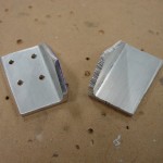
Final job for the day was fabrication of the rudder stops.  I’ve said this before, but I am very glad to have a bandsaw in the shop now, as it made fabrication of these angles pretty trivial.  I made the rear bit intentionally oversize, to leave a fudge factor for filing down when fitting.  I first fabricated the left stop and fit it to the fuselage, filing away until I hit the required 35 degrees of swing.  Then I simply created a mirror image part for the right side, again leaving some extra material on the rear face for filing.  These turned out nicely, and I’ve left them clecoed in place for now.

Fabricating rudder stops Left rudder stop fitting

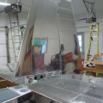
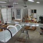
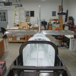
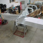
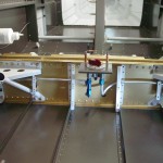
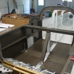
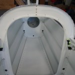
A couple pictures of the fuselage with the tail attached…  The book says this is a good time to fit the empennage fairing, but I think I will skip that for now and do it when I do the tips, to keep the glass work together once I’m set up for it.

Overview of tail install Overview of tail install

Hours: 7.5 | Posted in Wing & Tail Joins | Comments Off
28th June 2010

Building the tail

First things first, a plumbing tweak.  I was stumbling around on VAF last night on a completely unrelated topic when I came across a thread about fuel vent routing.  Those lines that I was so happy with had to be adjusted, because I ran them to the top of the bulkhead at a 90-degree angle, which would later interfere with the mouting of the subpanel.  This post has a picture which illustrates the issue.  Not a big deal, I just removed the adel clamps on the aft vertical run, undid the bottom fitting, bent the correct angles at the top, then trimmed the lower portion of the line and re-flared.  The plumbing is really done now…I think.

Fuel vent line with correct 45* bend

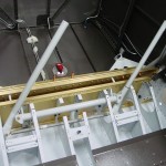
Nextly, back to work on the aft end of the plane.  I finished drilling up the holes in the horizontal stab, then attached the elevators and fitted the counterweights.  The right elevator is a bit nose-heavy, while the left is almost dead-on balanced.  Supposedly, nose-heavy is the way you want to be before paint, since there is more surface area (thus more added paint weight) aft of the pivot point.  Clamped the counterbalances to the stabilizer in preparation for fitting the pushrod.

Horizontal stab drilled to fuselage Underside of forward HS attach bolts Elevator horns and center bearing

Elevator counterweights bolted in HS and elevators in place

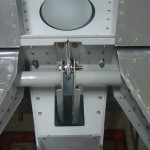
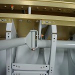
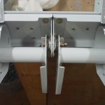
Since the pushrod needs to be fabricated and primed, I took a diversion next to install the control column.  This meant attaching the pivot brackets to the spar, then building the control column on top of them.  This task is complicated by all the various washers to be installed, and I had to fiddle with a few different combinations in order to get it to move smoothly.  After a final test fit and adjustment (these were initially fit during assembly of the center section bulkhead), I greased up the brass bushings and bolted the sticks in place.  I should be able to install the grips and wiring without removing them (crimp the pins, slide the wires down, then insert the pins in the connector), but I’m leaving the cotter pins out for now just in case….it’s s tight space and I’d rather only fiddle with cotter pins in there once.

Control column installed Detail of control column mounting

Hours: 4.9 | Posted in Plumbing, Wing & Tail Joins | Comments Off

28th June 2010

Horizontal stabilizer mounting

I decided to go ahead and proceed with the rigging of the tail surfaces, in preparation for wiring the tailcone before riveting the aft skins.  Tonight I pulled out the horizontal stabilizer and elevators and got to work.  First, the bolt holes needed to be drilled for the center pivot bearing on the elevators…I didn’t do this when I first fit the elevators to the stabilizer, because a 1/4″ spacer is needed to serve as a drill bushing, and I didn’t have any.  Now, I have lots of scrap pieces of 1/4″ tubing–which actually is a bit too large to fit the hole in the bearing, I turned it down by chucking it up in the drill press and using sandpaper.  A #14 drill fits nicely in the inner diameter, so I used that to drill the bolt holes, then enlarged for the 1/4″ bolt.  Next, the control horns get drilled for the attachment of the pushrod, using the plan dimensions on the aft-most horn, then match-drilling the other through a block of wood to keep the hole perpendicular.  All of this required several on-off cycles of at least one elevator, so I was glad to still have my bent nail temporary bolt gizmos I made when did the initial fitting 3 years ago.

Center bearing bolt drilled Drilling first elevator horn Clamped for drilling second horn

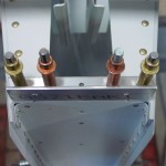
With the holes set for the elevators, off they come in order to mount the horizontal stab to the fuselage.  I put the stab in place and clamped it, then checked it for square by running a steel tape forward to a consistent point (I used the vertical of the spar carrythrough; my tape wasn’t long enough to reach the firewall as suggested in the manual).  I also checked left-right alignment to be sure it was on the centerline.  Both measurements were very close (within less than 1/16″) on the initial “eyeballed” fit, so a little tweak and it was good to go.  I clamped it to the aft deck and marked guide lines on the forward attach brackets and drilled them one hole at a time, moving clamps as required, first to #30, then to 3/16″ for the bolt.   (Finally, we’ve put the last holes in these brackets, the very first parts which are made at the beginning of the build…it’s interesting to ponder how that first encounter with “fabricate” seemed scary–I re-made those brackets, as many do–and now, “fabricate” just means “oh, okay” and another trip to the bandsaw, sander, file, and scotchbrite wheel.)

Mounting HS to fuselage HS forward attach angles drilled Mounting HS to fuselage

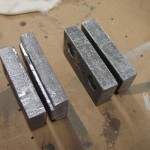
Trimmed the elevator counterweights on the bandsaw, a job that I started a few years ago and set aside because my hacksaw just couldn’t deal with cutting the lead blocks.  Bandsaw made quick work of them, with an old file to deburr the edges.  Finally, I cut the spacers that go under the HS attach angles and left them to cool for finishing on the next session.  I also need an 11/32″ drill bit for setting the rear HS spar incidence (it’s used as a precision spacer)…the closest I have is 21/64″, so perhaps I’ll stop off at a hardware store and pick one up.

Elevator counterweights trimmed

Hours: 3.9 | Posted in Wing & Tail Joins | Comments Off
26th June 2010

Fuselage plumbing victory

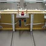
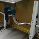
First order of business tonight was to attend to the misplaced fuel lines.  It turned out okay to pull them out from the inside, then re-run them in the correct holes.  Due to the differing geometry of the bends, the left line was re-usable, but the right line, when re-run and bent to mate with the selector, was too short — only about 2″ protruding from the fuselage, instead of the 4″ I was aiming for.  (Notes from other builders indicate that the necessary length is around 2 5/8″.)  So, out came the right one and I re-made a fresh line, using the coil of tubing I had set aside with the fuel pump output bend in it.  I cut it to the approximate length I needed, using the removed line as a guide, and it looks like there will be enough tube left to complete the run to the firewall, which is good news.  Crisis averted.

Fuel lines re-run in correct holes Detail of fuel lines below selector

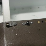
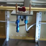
Next on the list was the brakes.  I finished fabricating the parking brake valve bracket, drilled the holes for the valve mounting bolts, drilled for nuplates, match-drilled the firewall (nutplates will go on the forward side of the firewall so that insertion and removal of the valve won’t be a two-man job, especially should it need to be removed for service).  I set this up to have the control cable go off to the left, as I liked what I saw in some panel photos today that had the parking brake control tucked under the panel and forward, along the left side of the cockpit.  It makes sense to keep it off the panel, being a not-often-used control.

Test fit of the brake valve looked good, so I installed the appropriate fittings and went to work on the brake lines.  Bending the lines around the angles at the firewall took some conjuring, but it wasn’t all that bad. Once the bottom tube (which will be the left brake) was made, the top one was essentially the same, with adjustment in the bend radii as needed so the tubes would essentially parallel each other.  I bent the front half of the tube, then estimated the length for the run along the spar, cut, bent the transition, and ran the tube out to the gear tower.  Repeat for the right side.  Installed the bulkhead fittings in the gear towers, as well, so that end of the lines could be torqued in place.  The valve end of the lines will wait until later, since the valve bracket still needs to be primed and riveted.

Brake lines and valve test fitting Brake lines at firewall Brake line outboard end Fuselage plumbing essentially complete

Hours: 4.9 | Posted in Plumbing | Comments Off
26th June 2010

A step back on fuel lines

Well, maybe the ease of installing those fuel lines yesterday was a sign that something was amiss.  I realized after looking at some pictures on other web sites that I ran the lines through the largest (top) bushing, thinking biggest tube = biggest bushing.  Not so…the largest bushing is for the wiring bundle.

Not a problem, right?  Just get some 3/8″ vinyl tubing, slit it lengthwise, and slide it over the tube into the bushing to take up the space and provide cushion, then pull the bottom bushing, drill out the hole, and install another large bushing.  Not so fast, according to a thread on VAF:

It is only Kosher if you don’t run any wires under it. Should you have a leak, the fuel could drip on the wires and that may not be a good thing.

Any Tech Advisor worth his salt would ask you to move the fuel lines to the bottom holes.

[...]

….don’t run the fuel lines above the wiring….it’s not acceptable aviation practice (ie very dangerous).

[...]

When in doubt you can always refer to the bible (AC43.13). Section 8 says: “Where practical, route wires and cables above fluid lines”.

Vans RV7 DWG 11 also specifically notes that the bottom snap bushing in the relevant cover support ribs (F-783B and F-783B) is an SB500-6 for the 3/8″ fuel line. The top snap bushings are an SB625-7 for the electrical wires.

Sigh.  Looks like I’ll be ordering another spool of 3/8″ tubing.  I almost put one on the last order…wish I had, it would have been a guarantee that the first time would go perfectly and I’d never need to touch the extra.  I don’t know that I’ll be able to pull these out intact and have them be the correct length, etc.

Posted in Plumbing | Comments Off
25th June 2010

Fuel lines & other fuselage miscellany

Finally conquered the selector-to-filter line, after the umpteenth iteration.  I ended up not using the swivel elbow on the filter inlet, because the short tube was impossible to bend and have room to slide the sleeves on and flare.  (The Rolo-flare, plus the sleeve, requires about 1 1/4″ of straight tube at the end to accomplish the task.)  Once that was done and in place, I mocked up the required bend to get the pump outlet routed down under the tunnel cover, with a piece of scrap, then replicated that in the end of a long piece of tubing…that’ll sit on the shelf for awhile until I determine where the firewall penetration fitting will be, at which time it will be run up there.

Selector-filter tubing Pump output tube

With the selector and pump solidly in hand, I moved on to the tank-to-selector plumbing.  These are the lines everyone talks about, that they’re so difficult, and the latest fad has been to use flex hose instead.  I actually found them rather easy, but maybe that was just relative after the three-day battle with the aforementioned connection.  I ran the spring bender through the side skin and the gear tower, then fed the tube in little by little, guiding it through the snap bushings until the end was at the fuel selector.  Bend as required, flare, done.  Repeat for the other side.  The right is slightly different than the left, as I have provisioned a tee for the AFP injection purge return line into the right tank feed line, just below the selector.

Fuel plumbing in place Tank feed lines installed Right tank feed line through weldment

Took a moment while I had the fuselage on its side to install and torque the elevator bellcrank.  Also trimmed the aft end of the canopy decks, which I had somehow missed in the earlier trimming…this removes the bit of the piece that would otherwise cover up the outboard portion of the canopy latch hole in the gusset plate below.  Easy with the Dremel tool and a cutoff wheel, followed up by some small files & scotchbrite.

Elevator bellcrank Trimmed end of canopy deck

Next was fitting the center tunnel cover…this wasn’t as bad of a task as I had been fearing.  The firewall recess was clecoed in place, then the tunnel cover set in place and measured for the proper spacing from the bottom skin.  #30 holes were drilled at four locations on each side, then enlarged to final size, and the holes were drilled into the firewall recess.  Cover was then removed and split in half, to allow the front portion to be installed separately from the aft portion.  This is necessary because the fuel line goes under midway up, forward of the boost pump, rather than under the selector.  All pieces deburred, nutplates drilled and installed, heater box louvers bent, then checked for fit again with all the rest of the pieces, boost pump, and tubing…very happy to see that the selector-filter tubing still fit correctly.  Removed covers and set aside for later.

Center tunnel cover Louvers in heater box Center tunnel cover temporarily in place Cabin fuel system test fit

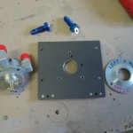
What’s next…brakes!  I have the new Matco parking brake valve, which I plan to install in the same place that the bracket on the firewall is (using the valve as the transition point from flex lines to solid lines) — so the first step was to drill off the existing bracket.  Next, I need to fabricate a bracket that has a provision for fixing the control cable in place.  I drew out, cut, and bent one that holds the valve horizontally (so the lines enter left and exit right), with the control cable coming from the right of the valve.  Not sure that’s where I want the control, so I’ll be looking at what others have done to mount this thing.

Attempt at brake valve bracket

Hours: 7.9 | Posted in Plumbing | Comments Off
24th June 2010

Macaroni tubing

More time today trying to wrangle the dang selector-filter tube into place.  I put a swivel elbow on the filter — the vertical of the elbow and the outlet of the selector are misaligned by about 3/8″, which means that the tube needs to have a joggle in it…maddeningly difficult to bend, as the short, short bit of tubing (only about 4″) provides very little leverage for bending, and it’s just too short to fit in the lever-type bender.  I had one piece nearly right, just a touch too long…cut it down and it was too short.  Argh!  I almost had another one fitting well, when it was time to leave for the evening’s entertainment.  I’ve probably used up 6-7 feet of tubing for this 5″ distance.  Simply amazing.

Note to future builders installing Andair selectors along with Andair pump/filter assemblies: don’t blindly use the measurements in the Andair drawings!  Set it up and think hard about this tubing run, and you might find it easier to use the tubing run to adjust the fore/aft position of the pump.  If I had set the pump 3/8″ farther forward (which would fit just fine), I could have used the swivel elbow and a nice, easy piece of straight tubing.  Live and learn…

Hours: 0.9 | Posted in Plumbing | Comments Off
23rd June 2010

Fuel pump installation

Worked on the fuel pump doubler, bracket, pump install, and selector-pump tubing.  Fabricated a doubler to go under the tunnel cover for support of the pump, out of a piece of .063 stock.  This will be riveted to the tunnel cover, then the pump will attach via screws/nutplates, and the shortened pump doghouse will attach over that.  i think it should work out well.

Fuel pump on tunnel cover, doubler is underneath

Much frustration ensued with the seemingly easy tube between selector and filter, but the short distance and radius of the bends actually make it very difficult, because the bottom bend must go nearly 180 degrees, then a 90 back vertical, and the distance between the flare and bend is very short, making flaring a challenge.  I gave up after 4 tries, which usually ended up with flattened, bulging, or kinked tubing.  I think a better option may be to use a swivel elbow on the filter inlet, and a “joggled” vertical tube between the selector and the elbow.  I have the elbow for another task, so I’ll try that–I can always order another if it works.

Hours: 3.9 | Posted in Plumbing | Comments Off
22nd June 2010

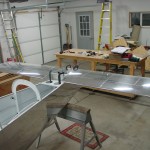
Full day of fuselage

Lots of little tasks to keep going on today…

Riveted the canopy decks in place!  This may come back to bite me later, but the instructions have this done long ago, and reaching over the fuselage witht he clecoes stabbing me in the gut was getting old.  Bucking these was actually quite easy; the tungsten bucking bar fits in the gap for all but the 4 rivets just aft of the spar upright, and for those, I just inserted the bar into the “channel” farther aft, positioned it horizontally (completely inside the channel), then slid it forward and held it up with my fingertips through the gap.  Method of assembly: completely remove the canopy deck and gusset, set all the rivets on the forward side of the bulkhead that hold the thick angle on the back, then install the gusset and rivet the 4 rivets on the top.  Finally, put the canopy deck back on and set all the rivets along the longeron.

Canopy decks and gusset plates installed Canopy deck installed Canopy decks installed

Turned threads off of fuel vent fittings by chucking them up in the drill press; made the angle cut, and deburred.  Still need to find screen and attach it before these can be installed for good.  Installed fuel vent lines from vent fitting, to stub through fuselage side to tank.  Installed rubber grommets through side skin.  I spent quite awhile bending the first one to fit right, then the other side was very easy, just duplicate it in mirror image on the bench, and it dropped right in with only minor tweaking.

Fuel vent lines bent, ready for installation Fuel vent line at bulkhead Bottom end of fuel vent line Fuel vent fittings

Installed rudder cables in the fuselage, and adel clamps at aft end.  (Need to torque and mark those screws.)  The string I had run earlier in the baggage area worked perfectly.  Installed the swivel fittings into the static ports and ran the static line between them, including the tee.  Ran static tubing forward, leaving a coil stored along the side of the fuselage with plenty of length to connect to instruments later.

Rudder cable installed Aft static plumbing installed Detail of static plumbing

Installed the flap actuator center bearing block nutplates, followed by the flap actuator, motor, and side covers.  Removed the side covers and set aside for later.  Need to order the Ray Allen POS-12 flap position sensor, which will mount somewhere in this area.

Installing flap bearing block nutplates

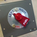
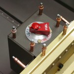
Installed Andair fuel valve to selector plate.  Used AN3 bolts for now, later I will probably replace this with different #10 hardware, some sort of more attractive screw.  Need to order more K1100-3 nutplates, since I stole from the supplied stock to mount the fuel selector.  Removed the elbow fittings from the selector, lubed the o-rings with EZ Turn, reinstalled, and staked the screws.  Like everyone else says, this valve is a work of art, and it’s hard to resist playing with the knob…no wonder it comes with a big red tag attached warning against “excessive dry operation.”

Andair fuel selector installation Andair fuel selector installed Staked screws on fuel selector Fuel selector trial fit in fuselage

Cut down height of the boost pump “doghouse” cover by 1 1/4 inches, since the Andair pump is not as tall as the stock (AFP) pump and all the tubing/accessories that go with it, and more open cabin space is better.  I could probably have cut another 1/2″ off of it, even.  (By this point, it was getting late and I was working without stopping for many pictures.)  I used the opposite cover to mark a cut line 1 1/4″ down from the top of each, then cut and deburred, then used the cut off piece to re-drill the hole pattern in the top of the shortened side.  This seemed easier than cutting from the bottom and re-bending the flange as I’ve seen others do.

Modified pump doghouse test fit

Began work on fuel pump installation, looking at how it will all fit together, and printed off the installation diagrams from Andair’s site for reference.

Hours: 11.0 | Posted in Cabin & Interior, Plumbing | Comments Off
20th June 2010

Gear mounts, gussets

Finished the gear mount install by drilling the right side skins and bolting in place.  The right side weldment had a gap between it and the fuselage side (not uncommon, or so I’ve read), so I fabricated a shim out of some scrap stock, to fill the gap and prevent the side skins from bowing in under the torque of the bolt.  As a result, I upsized the bolts and added a thin washer, to get proper thread engagement.  Drilled and countersunk the forward holes, and installed those screws as well.
Next, I re-installed the brackets that hold the cover plates ahead of the main spar; the bottom screw is tricky to get in, as the screwdriver can’t get a straight shot due to the tube of the gear tower being in the way.  I tried a number of types of screwdrivers, including a right-angle gizmo, but a thin-shaft regular driver ended up working the best, even though it was cocked at an angle.  The clockwise side of the head got a bit boogered, I believe, so these screws will be one-time use: if they ever need to come out they will be replaced.  I also sanded a curve into the bottom of these brackets, to provide additional clearance to the gear leg tube which is very nearby, and was barely rubbing on the right side.  Test-fit the forward covers and filed the slots at the bottom slightly, to provide better clearance from the floor stiffeners.

Looking around for other odd tasks, I decided to put in the gusset plates that reinforce the seatback brace-main longeron joint, and drill those holes to final size for rivets.  Five holes per side, not difficult; the forward two on each side are countersunk.  Those plates are now clecoed in place, and I believe the canopy decks can be riveted at any time.

Right gear mount installed Upper fuse gusset plate

Hours: 3.0 | Posted in Cabin & Interior | Comments Off