17th
June
2012
Not a ton of progress today, because I switched vehicles with Allison and in doing so, forgot to load up the stuff I needed to get started on either of the two major projects I was considering. So instead, I worked on some smaller stuff.
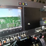
I’m not using two of the three switched aux inputs to EFIS 1, and I want to have some way of marking data in the log files during flight test (for use in calculating performance or looking at some specific occurrence in more detail). I checked the logs files and it turns out that the state of the inputs is logged. So, I decided I would install a simple toggle switch that I could flip to mark data, which I could find later by looking at the logged state of the input.
I have a blank panel I made to cover the open mounting tray for EFIS 2, so I drilled a 1/4″ hole in it and mounted a miniature toggle. Opened up the D-sub connector on the EFIS and swapped the pin in (the other side of the switch is connected to ground). I programmed the EFIS to display “Data Marker” on the screen when the switch is on. It’s not super pretty, or match the rest of the panel, but it is not intended to be a permanent install — just for gathering test data. I’ll remove it completely when I install the second EFIS someday…unless it proves to be amazingly useful for some reason beyond my expectations.
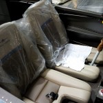
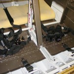
Decided for selfish reasons to do some work on the interior — secured the seat pans with several screws each (they’ll be removed for inspection again, so no reason to put them all in…it will be nice to have a seat, though, to do the engine runs). Pulled out the seat cushions and installed the velcro patches on the seatpans. I need to find the stick boots…
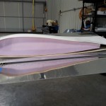
The rest of the session was back on the wings. I made a pair of foam ribs that match the airfoil shape, to use inside the wingtips. Also looked at the wingtips to see how they would need to be trimmed, and swapped around some pieces of hinge in preparation for mounting the tips.
Moving to the inboard end of the wings, I deburred & dimpled the screw holes in the wing root fairings, and mounted them in place. I marked a line 5/16″ or so from the side of the fuselage, down the entire length of the fairing strip, then removed and trimmed to the line. Filed the edges of both strips, and brought them home to finish the edges on the scotchbrite wheel.
Milestone: not only is it our 6th wedding anniversary today, but I also crossed 1800 hours logged on the project. That’s an average of 300 hours per year…thank you, dear, for tolerating & supporting this crazy idea of mine! We’ll go flying soon.
Hours: 5.1 | Posted in Cabin & Interior, Electrical, Endgame, Wing & Tail Joins |
17th
March
2012
Another warm day (but this time breezy and hazy as well). Trying to cross things off the list…
First on the agenda: loaded up the empennage and moved it to the hangar, where it will wait with the wings until final assembly.
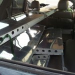
Next, set up the day’s fiberglass job. Added a couple plies to the nose flange layup from yesterday, to give it more stiffness. Closed off the inboard ends of the cooling inlet ramps with a 2-ply layup. Added flox to a couple spots and deep voids. Again today, I meant to get two rounds done, so one could cure overnight, but ran out of day.
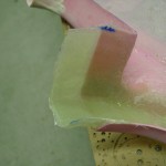
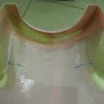
Spent awhile fussing with canopy seals. The edge-gripper bulb seal I wanted to use on the front seems a bit too thick, as it’s interfering with the closing of the canopy — the latch requires immense force to actuate. So, that was removed for now. I added the same bulb seal to the side rails, and that also cause latch trouble, so I ended up slicing the bulb in half for about 60% of the length of the side rails. It looks ragged when open, but seals fine when closed. This is easy to replace later — I’m searching for a smaller bulb, but the 3/8″ is the smallest I’ve found so far. I may have to explore using foam strips or something. Also ran into trouble with the rear rollbar seal, again, difficult to close & latch. Will explore more seals; it seems this is a spot everyone struggles to make work.
On to the “little stuff:”
- Slipped some clear tubing over a couple fluid lines in the tunnel to prevent any possible chafing from wire bundles (clearance is fine, but vibration does things…)
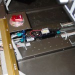
- Installed the fuel selector & torqued all the fluid fittings in the center tunnel.
- Installed the fuel pump and torqued those fittings.
- Installed the metal plug in the hole that provides access to the nose leg bolt. Sealed up with a good layer of firewall sealant on both sides.
- Installed the bolts on the RH lap belt, having received my order of hardware from Spruce.
- Finished off the firewall wiring passthrus per instructions, since wiring is complete.
- Torqued the forward bearing on the aft elevator pushrod.
- Checked that all bolts on the flight controls were torqued, and torqued them where they were not.
- Swept the shop and put away tools, brake bleeding stuff, and so on.
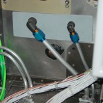
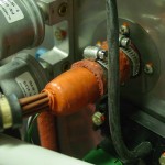
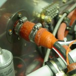
Hours: 8.0 | Posted in Cabin & Interior, Canopy & Frame, Cowling & Baffles, Engine, Plumbing, Wing & Tail Joins |
11th
March
2012
Several list items in this weekend’s work session.
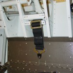
Having received the 1/4″ threaded drill I needed, drilled & deburred the crotch strap mounting holes. Installed the crotch straps. Drilled 1/4″ attach holes in the lap and shoulder belt attach points, and mounted those (RH lap belt temporary, as I ran out of the correct length AN4 bolts).
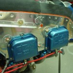
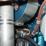
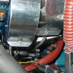
Final-installed the baffle screws with lockwashers. Replaced temporary nuts with metal locknuts on baffle mounting brackets. Fabricated and temporary-installed the baffle tension rods (need #6 metal locknuts), with nylon tube over the middle parts; they don’t contact anything as is, but should something shift, the nylon will prevent wear until the next inspection/oil change/etc.
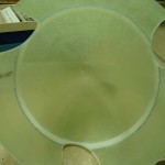
Applied packing tape to the forward spinner bulkhead, laid a bead of flox on the inside of the spinner at the contact point, and clecoed it in place. There was a moment of concern when the spinner didn’t want to release from the tape after curing for a few hours–I wanted to let the flox set up to hold proper shape before removing the spinner. After pushing, prodding, tapping, and finally whacking it on an angle (it took quite a few good double-fisted whacks…that’s a strong piece of fiberglass…), one section popped loose and I was able to work it free. Trimmed the squeezed-out flox off with a knife, to save weight and keep the spinner as balanced as possible, since this is part of the rotating mass.
Hours: 8.3 | Posted in Cabin & Interior, Cowling & Baffles, Engine |
5th
July
2011
Just a bit of time in the shop after working 9 hours during the day on other things…what vacation? Riveted in the panel brace, reinstalled EFIS 1 and connected the AOA tubing, mounted the ELT bracket, and clipped some wireties from a previous session, along with the usual staring at the project to see what’s next.
Hours: 1.6 | Posted in Cabin & Interior, Electrical |
13th
March
2011
Spent some time sanding, smoothing, and scuffing the panel, then shot it with primer. An hour later, sprayed the flat black finish coat. Brought it inside for the night to dry in the warm(er) house.
Hours: 2.0 | Posted in Cabin & Interior |
27th
February
2011
I often find myself bouncing around the project lately, where I may be working on three little jobs at once in different parts of the shop…waiting for paint to dry on a couple things, for instance, while drilling something and wiring something else. So when I sit down at the end of the day to write these logs, it’s sometimes challenging to think back and remember everything I did that day. Pictures help, but I’ve had a bad time remembering to take a photo of every little job, too.
Today’s work…
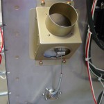
- Riveted the right cabin heat control bracket to the vent bracket, which was then riveted to the side skin. Installed the control cable and secured it, which required some modification to the firewall passthru, as the cable was just slightly loose in the eyeball. I used a flat file to shave just a bit off the flat side of each ball halve, which allowed it to get a firm grip on the cable and secure it in place. Cut the casing and cable to length and assembled. Installed the right side vent nozzle.
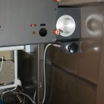
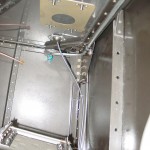
- Traced the spare round-gauge hole, and the autopilot head hole, onto scrap stock and cut it out to make filler panels for those cutouts, since they will not have instruments installed in the until phase two of the panel.
- Fabricated angles for mounting the radio stack to the panel. Waiting to drill them to the panel until the radios are in hand, in case the width of the trays is a bit off of the width of the panel cutout.
- Cut a hole in the subpanel behind each EFIS screen to pass the wiring harnesses and pressure tubing. Also put a hole in the lower right subpanel for the wiring feeds to the switches on that side of the panel, in addition to the hole that’s already made for running cable to the dimmer module. I have a couple sizes of nice rubber grommets from McMaster, in addition to an assortment of snap bushings that I bought from Van’s awhile back; finding the right size for a particular hole is easy.
- Wired up the dimmer pots and interior light switches, then dropped the panel in to test them out. While the panel was in, I ran wire for the accessory power jack and the music input jack next to it (though this wire may end up being a placeholder, if this wire is already in the harness from Stein).
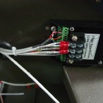
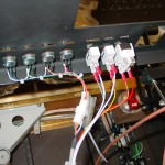
- Ran a wire to each Pmag for the serial port connection. I will bring each of these to a jack on the subpanel for ease of connection with the computer utility. The rear-mounted APRS transmitter will have a similar jack on the baggage bulkhead for programming.
- Test-fit the CO/SpO2 sensor. Can’t use washers on these screws, because the mounting holes on the piece are too close to the protruding bezel. Decided I need to get some #10 capscrews for the throttle quadrant mount to the panel, which should work better than bolts due to clearances (sockets were getting wedged in place).
- Cut the plastic U-channels for the switch backlights, and painted them black. Cut LED strips to length for each piece of channel (3 total), and soldered leads to them. After testing them, it looks like another layer of paint will be necessary; the light bleeds through the sides of the channel.
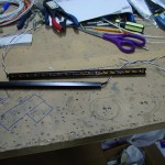
Hours: 6.9 | Posted in Cabin & Interior, Electrical |
26th
February
2011
Spent the day working on various items, mostly in the cabin area.
- Hooked up the Garmin GPS 18x-5Hz to power and a computer to program & test it out. Solid lock even inside the house.
- Printed real labels for the various wires I had labelled with tape after I ran out of label stock.
- Installed a connector on the #2 OAT sensor, installed it in the wing, and added connectors to the wing end of the OAT cable for both sensors.
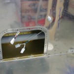
- Drilled the #2 EFIS tray to the panel, the #1 tray will come with the avionics order…hopefully next week!
- Deburred and primed the panel and riveted the top angle on, after removing a bit of one ear on the angle to allow for the #1 EFIS tray.
- Riveted the canopy seal support angles to the subpanel.
- Removed the right side panel-subpanel rib as I did earlier on the left; though I spaced the radio stack to not interfere with the rib, the angle to mount the stack would overlap the rib, and there would be no clearance for the mounting nuts. This could be shortened by the thickness of the angle and mounted behind it, or (easier) moved to the right by 3/4″ of an inch of so.
- Added nutplates to the panel flange, and the subpanel bracket, to bolt the throttle quadrant mount to. I’m making a conscious effort/decision to use nutplates under the panel, and have bolt/screw heads face down, so that future maintenance will be easier. Also any electrical connection that must be made with solder (such as master and starter switches) will have a connector inline, to allow the component to be removed and serviced on the bench, rather than soldering in situ, laying on my back working over my head.
- Fabricated a bracket that straddles the throttle quadrant, to allow mounting of the fuel purge and center cabin heat controls on either side. Painted and temporarily installed with the quadrant to work out cable routing. Quadrant and bracket are mounted via the same bolts, and the bracket dresses out the quadrant install well, I think.
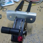
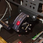
- Finished installing the firewall eyeballs for the throttle, mixture, and center cabin heat controls. These buggers are time consuming…but only two left (purge & alt air).
- Fit the center cabin heat cable and figured out the cable route. Put the right seat in to sit and work out a location for the right-side heat cable. Decided to put it under the right air vent, against the sidewall. So, fabricated a mounting bracket and painted for installation tomorrow.
- Riveted the left side vent bracket in place and installed the vent. (Right side tomorrow, after the heater cable bracket is attached to it.)
Passed 1200 hours in this session.
Hours: 9.1 | Posted in Cabin & Interior, Electrical |
22nd
February
2011
Panel placards arrived today, they look good. All the holes are perfectly aligned with the panel cutouts, so the drawings and CNC cutting worked well on both ends.
Primed & painted a few small pieces for installation in the next session.
Hours: 0.8 | Posted in Cabin & Interior |
21st
February
2011
Cleaned up the bench and found the countersink cutter, so I countersunk the vent brackets and panel top, then pulled everything apart for deburring and primer. The panel won’t be primed/painted yet, as it will need more drilling and such to mount the avionics.
Wired the map lights and baggage lights to the dimmer module, temporarily connected the dimmer pots, and put some power to it; it’s fun to see things light up. I also clamped an LED strip along the bottom of the subpanel to test if it would work for cabin/footwell lighting. It did, so I installed that as well, though the wiring is not yet final.
Drilled the large holes in the firewall for the throttle, mixture, and center cabin heat cables. Tomorrow I’ll drill the screw holes to hold the eyeballs in place.
Hours: 4.2 | Posted in Cabin & Interior, Electrical |
20th
February
2011
With the CNC cut panel in hand, I set to work getting it ready for installation. This meant that all the switches and stuff I put in for fun had to come out, but I knew that was coming. First, I drilled the holes for the RH panel rib using the stock panel as a template. I discovered that the panel was rubbing the canopy deck on the right side (I’m guessing that the canopy decks and/or longeron heights are not 100% symmetrical), so I trimmed a bit of material off the edge to make both sides match and fit nicely.
The big piece to fabricate (it’s been awhile since I had a “make from” instruction) is the reinforcing angle which runs along the top of the panel and stiffens it. This is just a piece of 3/4″ leg angle, but it it tedious to make because it needs a bunch of slots made in it to allow it to bend around the curve of the panel top. While I was on that sort of a track, I also finished up the canopy seal holders which needed the same treatment. I ended up drilling the radius holes with a #30 bit (R-1/16) on the drill press, then marking lines for the 15* slots and cutting with a hacksaw, as the angle is too long for the bandsaw. Clamping to the bench and filing both sides, then the radius, finished it off; after that it was a relatively easy task to drill to the panel. That particular job ended there, as I can’t seem to locate my #40 countersink cutter. There’s also two small angles that run vertically at the outboard edges of the panel, so those were made and drilled too.
With the panel clecoed in place, I set to work on the vent brackets. I’m going off-plans here, since I am installing the SteinAir vents, which don’t mount with screws like Van’s vents do. I decided to cut a couple pieces from the stock panel blank, keeping the bottom flange, and nest the radii together with the vent bracket behind the panel. A piece of angle attaches the bracket to the side skin at the four pre-drilled holes. Easy enough in concept, but fitting it all up and drilling everything took some time. I also added an additional screw hole to the lower part of the panel that will affix it to the vent bracket; this should provide some extra solidity to the switch row.
Pulled the panel out and deburred the work that was done, then drilled the canopy seal holder angle to the subpanel. I’ll need to do a priming/painting job sometime soon here so things can be assembled.
One more project…installation of the throttle quadrant. I’ve mapped this out in my head, so it wasn’t that big of a deal, and it was fun to see it in the plane. I cut a couple pieces of angle to run from the panel to the subpanel, providing a place to attach the TQ–here I’m using hardware store angle as was suggested by someone on the forums, since it doesn’t have a radius on the inside of the vertex, which allows the TQ to seat firmly inside. Another piece cut from the stock panel blank provides extra length at the subpanel to compensate for the added length of the panel. Securing the angle pieces to that bracket with bolts will give a handy place to use adel clamps for the purge & cabin heat cables that will go to the outsides of the quadrant. The front of the angles are secured directly to the bottom flange of the panel. I was going to mount the quadrant on center, but sitting in the plane fooling with various positions, I ended up cheating it just a bit to the right, so the flap switch would be easy/comfortable to reach with my hand on the throttle lever. It’s only 1/2″ or so off center, so not very noticeable and not encroaching too much on passenger leg room.
Looks like I might be forced to clean the shop tomorrow so I can find that countersink bit…
Hours: 7.3 | Posted in Cabin & Interior |


