11th July 2010

Canopy latch, prep & prime

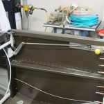
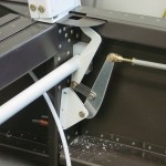
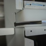
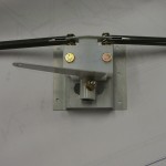
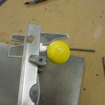
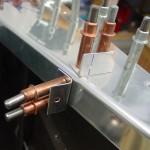
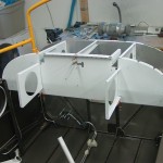
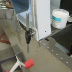
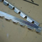
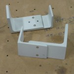
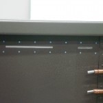
Finished off the installation of the main canopy latch by cutting the slots in the fuselage side skin; used the traced template to drill the pilot holes, then masked the area to be cut with blue tape, made two passes with a Dremel cutoff wheel, and worked with needle files to finish it off.  Not bad.  Drilled the mechanism to the skin, dimpled with the pop-rivet dimpler, and countersunk the angles, before fitting the aft part of the mechanism.  All in all, an easy piece of the puzzle, and it operates well.  I did have to slightly enlarge the aft slot top to bottom to prevent binding and scraping of the handle; I think there is a slight bit of variation to the straightness, and I couldn’t convince it any straighter.  No biggie.

Latch slots cut in skin Latch mechanism drilled in place Latch mechanism in place

Fitting latch mechanism Latch aft detail

Note: when you go to rivet the little screw plate to the top of the flap motor mount channel, use flush rivets, rather than universal heads…I ended up drilling out those three AD470′s and replacing them with 426′s, because they were rubbing on the torque tube for the canopy latch.  Even without the rivets, the tube rubs slightly on the channel; I think this is a common problem.  I’ll probably stick a piece of UHMW tape on the channel there to avoid chafing, unless a better solution comes to light.

Changed to flush rivets on flap assembly

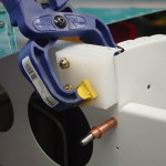
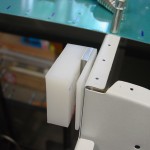
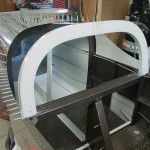
Pulled out the canopy frame to look at how it goes together; did a couple common things: filed the welds flush, chamfered the forward edge of the hinge ears, and chamfered the aft edges of the plastic hinge blocks.  This allows the ears to guide themselves into the slots.

Filed welds on canopy frame Hinge block chamfers

Time to check off the laundry list of little fuselage tasks to get ready for some riveting:

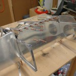
  • Removed the latch mechanism, disassembled for prime/paint, and deburred.
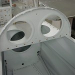
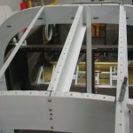
  • Removed the forward top skin and subpanel assembly, spot primed scuffs, and set aside.  Debating whether to paint the stuff aft of the subpanel or not.  (Note to self: still need to ream the outer bulkhead holes)
  • Removed the roll bar and brackets for prime/paint.  Deburred and cleaned up shavings from that installation; touched up paint on the trimmed corners of the seatback rests.
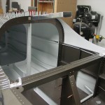
  • Removed the mid top skin for painting; lifted one side of the aft top skin for wiring/plumbing access.
  • Pulled the static line with the hole drilled in it and ran a replacement line.
  • Spot primed aft bulkheads and vacuumed the aft fuselage.

Etched and primed all the removed parts; rattle-can painted a few little things, waiting on the rest–I need to pick up another quart of the Rustoleum brown, because it goes on better with the sprayer than from the cans.

The plan going forward is to run some wiring in the aft fuse, then close that up, along with the structure of the subpanel, to prepare for fitting the canopy frame.

Hours: 9.7 | Posted in Canopy & Frame | Comments Off
10th July 2010

Canopy hinges & latches

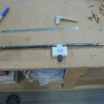
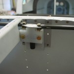
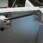
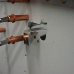
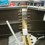
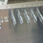
Spent most of today working on the canopy hinges and latches.  First order of business was to drill the 1/4″ holes for the pivot pins, using a 12″ drill bit I picked up.  That done, I built up the mechanism that inserts and retracts the hinge pins.  This required cutting off the threads and rounding the ends of the pins themselves, fabricating the pushrods, and assembling the bellcrank mechanism.  The goofed-up hat channel was replaced with a shorter piece, cut from the section that was cut off before.  This should work fine, since its only purpose is to hold the bellcrank…I had enough material left to pick up the top three rivets on each side.  Installed the lever on the bottom of the bellcrank, but not the tube that runs aft; instead, I made a little handle that attaches to the lever, and has a tab with a hole to secure it to the subpanel.  I put in a nutplate for a #8 screw to hold it there; a nice improvement would be a thumbscrew with a #8 thread, so that it would be easy to undo without having to mess with a screwdriver behind the panel.  This tab will be easily reachable, since this is open to the sky when the canopy is open.  (The tab idea was shamelessly stolen from another website, though I can’t remember where I saw it… Flyvans.com, also a good resource for tip-up canopy Sikaflex tips.)

Assembling canopy hinge pin mechanism Fitting hinge pin mechanism Hinge pin mechanism detail Hinge pin mechanism lever

Canopy release tab

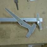
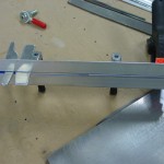
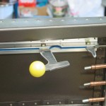
With that mechanism rigged, on to the next thing…the main canopy latch.  First up is to fabricate the control lever, which allows the pilot to latch/unlatch, and also protrudes through the side skin to allow the latch to be opened and closed from outside of the plane.  The upper and lower angles were fabricated, latch arms deburred and straightened, and holes drilled–bottom first, then match-drilled to the top angle.  (Hint: I use my back-rivet plate as a true surface to verify that things are flush if needed for match-drilling.)  I stacked up four layers of masking tape on the inside face of the angles to allow for the thickness of primer and UHMW tape to be applied later.  For fun, drilled the yellow latch knob to the lever.  And finally, traced the template for cutting the side skin, which I’ll get around to tomorrow.

Side latch fabrication Side latch handle assembly Latch knob drilled to lever

Hours: 6.2 | Posted in Canopy & Frame | Comments Off
9th July 2010

Subpanel & canopy hinges

Finished up the subpanel installation by fitting and drilling the angle clips that hold the outer corners of the instrument panel to the forward canopy decks.  Also drilled the center section cap strips to the vertical members; snapped off another 1/8″ angle drill bit, now I’m down to just the short stubby one.  I think this results from excessive bit wobble in the cheapo angle drill attachment…next time (ha!) I’ll splurge on a real angle drill with a small head.

Outboard panel clips Panel clips from behind panel Drilled cap strips

On to the canopy hinges…fabricated the plastic blocks and aluminum spacers according to plans.  Apparently, the stub ribs weren’t supposed to be riveted to the subpanel yet, since they need to be out of the way for some match-drilling at this step.  No big deal–I just removed the center portion of the subpanel, leaving the sides in place, and a nice open area in which to wield the drill…worked well.  Once the appropriate drilling was done, the center part went back in to be drilled.  I kept the top skin on for as much of this as possible, moved forward three holes when necessary to provide a gap to work/drill/see/clamp in.  I wasn’t able to drill the hinge pin hole through to the stub rib, because my 1/4″ drill bit is too short, and I can’t get the drill in the correct place to make a straight hole…I’ll pick up a longer bit, which should solve the problem.

Match-drilling hinge blocks Match-drilling hinge blocks Hinge blocks partially fitted

Hours: 4.7 | Posted in Canopy & Frame | Comments Off
8th July 2010

Fitting subpanel assembly and more

The big deal for tonight was fitting the subpanel assembly, which needs to be in place before the canopy fitting can begin.  Before putting this in, I clamped an angle across the firewall at longeron level, and bent the top section forward…I can’t find it anywhere in the plans, but Smitty’s log says the bend is 8 degrees, which is what I did, and it worked out perfectly.

On the bench, I riveted the “stub ribs” to the outboard subpanel sections, then clecoed them into the fuselage.  The center subpanel section then fits between the outer two and is clecoed in place.  I left the panel ribs full-size for now, and I’ll deal with them later on, once I know where everything will be in the panel.  With the structure in place, I fit and drilled the top skin, using the centerlined I had drawn on all the non-prepunched pieces earlier.

Outboard subpanel sections clecoed Center subpanel in place

Of course, with the panel ribs sticking out there, I had to cleco the panel in for a moment to see how it looked.  I wish I had seats to sit in it and check out the fit!  (Though my current panel plan has the bottom extended down by 1.5″…)  It looks more and more like an airplane, even if the cockpit does keep getting smaller.

Panel clecoed, top skin drilled

For kicks, I deburred the spar upright cap strips and slid them into place.  I don’t recall that the manual ever mentioned these, but other folks have installed them at this point with no ill effects.  Of course, they’ll first need to be drilled, deburred, and painted.

Cap strips fit, ready for drilling

Finally, back to the subpanel structure: I drilled the angle clip to the front of the center rib and the firewall, then set about fitting the forward canopy decks.  A pretty easy task, that, just go slow on the trimming–repeated trips to the scotchbrite wheel worked wonders, and gave a pretty tight fit between the forward and aft decks.  Word of warning: if you’ve already run your static tubing forward, remember that it’s under the longeron, and be careful not to drill a hole in it.  Oops.  Thankfully, I ordered plenty of extra and have enough left to re-run that piece; I can cut from the “holey” piece for any behind-panel jumpers I might need.

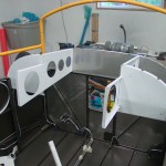
Forward canopy decks drilled Status shot

Rambling begins here: With the exception of fitting the wings, and locating a couple angle clips to attach the panel, I’ve come the the end of the fuselage instructions.  The canopy fitting starts next in the book, and from here, the project could take any number of paths with regard to the order of operations.  Canopy, electrical, avionics/panel, engine, fiberglass tips…the strict order of dependencies sort of disappears.  It seems that it can be taken in pretty much any order, as long as you think through the implications ahead of time, and are willing to live with the consequences.  I think the current plan is to do the canopy first, hoping to get it in the bag by the end of summer.  That will leave the winter for engine and electrical installs, and avionics prewire.  I may curse that decision later, while laying under the riveted subpanel trying to get all the wiring in place, but I think it’s the best decision for progress and cashflow reasons.  I’m planning on a trip to Oshkosh this year, to finalize decisions on all the components (though most of it is pretty finalized in my head already, if not on paper), and take advantage of any screaming deals that may be on offer.  Who knows, maybe I’ll get lucky at the Van’s demo ride line and actually get to fly in an RV, 1000 hours into the build!

Hours: 3.6 | Posted in Cabin & Interior | Comments Off
8th July 2010

The smell of primer in the morning

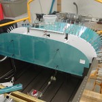
This morning, primed the subpanel components and dimpled where necessary for first fitting.  Also pulled the roll bar brace and associated parts, prepped and primed them.  There’s a stack of things awaiting finish paint now, that will likely wait for a bit.  I haven’t yet decided whether to paint the bits between the subpanel and the panel — they’ll be covered by the glareshield when the canopy is closed, but open for viewing with the canopy open.  Leaving the stuff ahead of the subpanel with just the white primer might be a benefit for later maintenance (white reflects light, and that cave area is accessed from underneath with a flashlight…), but the parts aft of the subpanel are all out in the open for maintenance access.  Hmm.

Hours: 2.0 | Posted in Cabin & Interior | Comments Off
6th July 2010

Primer prep

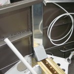
Etched the subpanel components for priming.

Hours: 1.0 | Posted in Cabin & Interior | Comments Off
5th July 2010

Roll bar install, subpanel

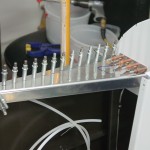
Completed the initial installation of the roll bar by fitting it to the fuselage and drilling, countersinking, tapping as required.  Some trimming of the aft ends was necessary for a good fit, as noted in the plans.  Clamped and drilled the connector channel and associated angles as well.  The roll bar is surprisingly solid, even without being completely bolted in.

Initial trimming of roll bar aft end Installing top roll bar support channel Tapping roll bar Roll bar temporarily in place

Next, on to the upper forward fuselage/subpanel area.  A  bunch of small angles needed fabrication, and the only snafu was when one pair fell off of the bandsaw into a bucket of waste oil…so a second set of those were made.  Fabricated the “stub ribs,” trimmed various things according to plans, and drilled them together.  The manual says “drill the hat channel to the aft face of the subpanel”…don’t do it!  Despite what the manual says, the drawings clearly show the hat channel on the forward face of the subpanel, and the hole pattern is slightly different left/right, so it can’t just be flipped…I’ll have to order a new piece.  For now, this isn’t critical (it is the bracket that holds the canopy jettison pivot assembly), so I drilled a few holes to hold it in place for spacing until a new one can be fabricated.  Finished up by disassembling the whole thing and deburring the bits…decided I didn’t feel like etching more parts (didn’t I just do that?), so I called it a night.

Assembling subpanel structure Fabricating outboard seal angles

I am seeing here where it would be expedient to have a panel plan in place (at least the instruments and radio stack locations nailed down) — things like the final location of the left/right panel ribs would be much easier to deal with on the bench than after parts of the assembly have been riveted in place.  I’m going to look at other folks with panels similar to mine to see if I can come up with anything…or I suppose I could cut the ribs flush and then wait until later to rivet in the forward portions (I know at least the left rib will need to move).  There are a couple almost identical to what I’m planning, but they are both sliders, so the structure is all different.

(900 hours tonight)

Hours: 8.4 | Posted in Cabin & Interior | Comments Off
4th July 2010

Priming and assembly

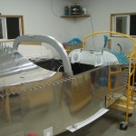
Primed the roll bar components and other misc bits from yesterday’s prep session.  Also deburred , etched, primed and dimpled the top skins and J-stringers, since they need to be in place for the roll bar fitting, to hold everything at it’s proper location.  I have not painted the roll bar parts yet, since there is still some fitting to do; I will paint it as an assembly in the next batch after fitting, along with the channel that holds it in place.

Once the primer was dry, the roll bar was riveted together, then the brackets were clamped, drilled, and riveted together, then fit and drilled to the fuselage.  Spacers were fabricated from .063 stock to go outboard of the brackets (yes, the angles are supposed to overhang the fuselage and be filed, but my roll bar ended up a bit narrower than expected, and this will actually work well to allow a gap for gluing the forward line of the rear window to the roll bar).  That is not a fun filing job.

Riveting roll bar Roll bar splice plates riveted

Drilling roll bar brackets Roll bar bracket assemblies Spacers to match fuselage width

With all that out of the way, I riveted in the 709 bulkhead and the top rib behind the baggage compartment, and clecoed on the top skins in preparation for tomorrow’s work.  I drilled the two holes from the top skin into the roll bar brackets and spacers at #40 for now.

709 bulkhead riveted Top rib installed Top skins in place Brackets drilled

Hours: 10.2 | Posted in Cabin & Interior | Comments Off
3rd July 2010

More roll bar fabrication, primer prep

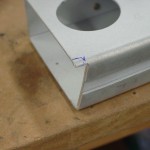
Finished fabrication of the roll bar by drilling the forward channel to the join strips, then took it apart for deburring.  Etched the pieces of the roll bar assembly, along with some other parts collected over the last couple weeks (boost pump doghouse, brake bracket, etc.)

Prepared to drill forward channel Forward splice plate drilled Roll bar drilled

Hours: 4.5 | Posted in Cabin & Interior | Comments Off
2nd July 2010

Roll bar fabrication

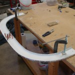
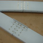
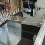
Started work on the roll bar (aka cabin frame) today.  Laid out and cut all the angle pieces and plates necessary, and figured out how it all comes together on the fuselage.  With those pieces at the ready, I pulled out the roll bar channels and designated them as fore/aft left/right for reference.  I marked out guide lines at the proper dimensions on the workbench, and went to work fitting.  I had to trim a bit from the inboard top end of each side to get the width correct; once that was done, the splice plate was drilled in place.  With the whole thing clamped and clecoed to the bench, I marked the top and bottom strips and drilled them in place, starting in the middle and working out, clamping between each drilled hole.  The angle drill attachment was necessary here, because of the proximity to the benchtop.  After both strips were drilled to the aft channels, they were removed for a quick deburring and chip removal, with the thought that it would allow for a better fit and more accurate drilling when the forward channels are added tomorrow.
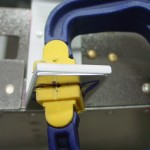
Drilling splice plate Drilling bottom join strip Bottom joim strip drilled to aft channel Aft channels drilled to join strips

Hours: 3.2 | Posted in Cabin & Interior | Comments Off