Fuel lines & other fuselage miscellany
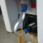
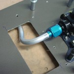
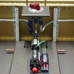
Hours: 7.9 | Posted in PlumbingFinally conquered the selector-to-filter line, after the umpteenth iteration. I ended up not using the swivel elbow on the filter inlet, because the short tube was impossible to bend and have room to slide the sleeves on and flare. (The Rolo-flare, plus the sleeve, requires about 1 1/4″ of straight tube at the end to accomplish the task.) Once that was done and in place, I mocked up the required bend to get the pump outlet routed down under the tunnel cover, with a piece of scrap, then replicated that in the end of a long piece of tubing…that’ll sit on the shelf for awhile until I determine where the firewall penetration fitting will be, at which time it will be run up there.
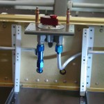
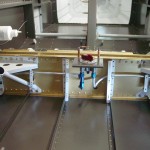
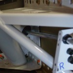
With the selector and pump solidly in hand, I moved on to the tank-to-selector plumbing. These are the lines everyone talks about, that they’re so difficult, and the latest fad has been to use flex hose instead. I actually found them rather easy, but maybe that was just relative after the three-day battle with the aforementioned connection. I ran the spring bender through the side skin and the gear tower, then fed the tube in little by little, guiding it through the snap bushings until the end was at the fuel selector. Bend as required, flare, done. Repeat for the other side. The right is slightly different than the left, as I have provisioned a tee for the AFP injection purge return line into the right tank feed line, just below the selector.
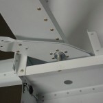
Took a moment while I had the fuselage on its side to install and torque the elevator bellcrank. Also trimmed the aft end of the canopy decks, which I had somehow missed in the earlier trimming…this removes the bit of the piece that would otherwise cover up the outboard portion of the canopy latch hole in the gusset plate below. Easy with the Dremel tool and a cutoff wheel, followed up by some small files & scotchbrite.
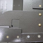
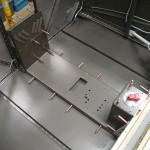
Next was fitting the center tunnel cover…this wasn’t as bad of a task as I had been fearing. The firewall recess was clecoed in place, then the tunnel cover set in place and measured for the proper spacing from the bottom skin. #30 holes were drilled at four locations on each side, then enlarged to final size, and the holes were drilled into the firewall recess. Cover was then removed and split in half, to allow the front portion to be installed separately from the aft portion. This is necessary because the fuel line goes under midway up, forward of the boost pump, rather than under the selector. All pieces deburred, nutplates drilled and installed, heater box louvers bent, then checked for fit again with all the rest of the pieces, boost pump, and tubing…very happy to see that the selector-filter tubing still fit correctly. Removed covers and set aside for later.
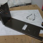
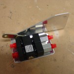
What’s next…brakes! I have the new Matco parking brake valve, which I plan to install in the same place that the bracket on the firewall is (using the valve as the transition point from flex lines to solid lines) — so the first step was to drill off the existing bracket. Next, I need to fabricate a bracket that has a provision for fixing the control cable in place. I drew out, cut, and bent one that holds the valve horizontally (so the lines enter left and exit right), with the control cable coming from the right of the valve. Not sure that’s where I want the control, so I’ll be looking at what others have done to mount this thing.
