4th March 2012

Moving on from tips

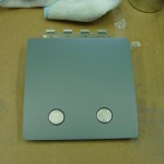
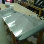
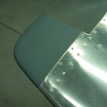
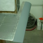
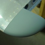
With the first batch of fiberglass parts done, today saw the attachment of all the empennage tips to their respective stabilizers and control surfaces.  The emp fairing was set aside for the day the tail is installed at the airport, and the spray booth collapsed until the next round.  The only remaining item for the emp is that the taillight screw holes on the rudder need to be tapped to remove some excess micro that got in them.  After that, the emp parts will make their way to the airport at some point, to wait with the wings for the Big Move of the fuselage.

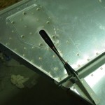
While working on the left elevator, also final-installed the trim pushrod and cotter pins.

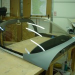
The plastic covering on the canopy was the original as shipped in the finish kit, and had become quite tattered, along with being covered in dust and overspray of all sorts — I removed it, and will cover the canopy with layers of saran wrap to keep it pretty in the interim.  Today, cleaned, prepped, and attached the canopy side skirt pieces to the canopy frame.  Currently, they’re clecoed in place to let the bead of Sika cure, then I’ll add the rivets.  Also fabricated the exterior canopy lift handle (pilot’s side only, thanks) and drilled to the frame.  The canopy is very static-y when cleaning with a microfiber cloth, which means it didn’t stay clean for long, but every dust particle in the shop was attracted to it.


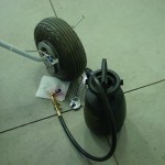
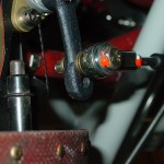
Re-bled the right brakes again, but still have a soft right brake pedal compared to the left.  I see no leaks, even under pressure, where air might be entering, so I can only blame the bleeder tank somehow.  Sort of disheartening, as the original system fill was rock-solid on both sides…too easy.  But the leaks at the pedals had to be fixed.  I wonder if draining the whole right side and refilling would provide better results.  I also wonder about the design of the bleeder valve, and whether air can’t find a path to enter there.

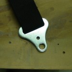
Decided to look at the installation of the crotch straps.  Pulled the seat pans and found that it would work well to simply drill a new hole in the crotch strap bracket, up from the giant factory hole.  I marked them in situ, and drilled both to 1/4″.  The geometry of this area requires an angle drill, but my largest bit is 5/16, so I will need to procure a 1/4″ threaded bit to complete the installation.

While messing around in the fuse with seatbelts, I happened to notice that four bolts were never put in the center section — whoops!  These are the bolts that go through the inboard tubing support brackets, just outside the fuel selector, top & bottom on both sides.  Obviously, I installed those bolts.

Hours: 7.2 | Posted in Center Fuselage, Gear & Fairings, Wing & Tail Joins | Comments Off
3rd March 2012

Topcoat fairings // brakes

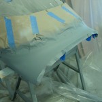
Two sessions today.  In the afternoon, sanded the K36 smooth — that stuff sands very easy — and sprayed a topcoat of DPLF epoxy primer, per the advice of folks at VAF, who say it is more resistant to oil, etc.

In the evening, came back to respray one elevator tip, whose finish was marred when the plastic sheet that makes up the paint booth perimeter fell on it while drying.  Argh, and it doesn’t look quite as good as the other, but good enough to last until the plane is painted for real…just trying to make sure the glass is protected and looks decent here.

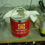
Also tightened one more leaking NPT elbow on the passenger’s left brake, and re-bled the left brake system.  Replaced the broken right brake bleeder screw, and re-bled that side, but there was a continual stream of tiny bubbles in the fluid and the right brake is definitely softer than the left.  I think pumping up the bleeder tank put bubbles in the fluid when the level in the tank got low, so I filled it back up and pumped it up.  I’ll leave it set overnight to allow the bubbles to settle out, and re-bleed again tomorrow; hopefully that’ll fix it.

Hours: 5.0 | Posted in Gear & Fairings, Wing & Tail Joins | Comments Off
14th February 2012

Lay on, sand off

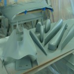
More fun with cowling to start the day: added some glass to a spot in the nose of the upper cowling that was thinned out by sanding, and laid up a couple plies at the sides of the oil door (+ peel ply).  Took the extra epoxy and squeegeed it on the inside of the top cowl.

Taking a break from fiberglass work, I filled the brake system with fluid.  This was pretty easy with the use of the brake bleeder tank I picked up from ATS, which came with the correct bleeder fitting for the calipers.  I filled up the tank with fluid, attached a NPT-to-hose-barb fitting to the brake reservoir in place of the cap, with a clear nylon tube to the empty fluid canister, and pumped away.  Once a stream of uninterrupted fluid had flowed out of the reservoir, I switched sides and repeated.  No leaks apparent, but I still need to climb in and test the system under pedal pressure, as well as check the operation of the parking brake.

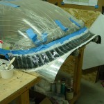
Back to work: spent considerable time sanding down the fillet of Sika at the canopy base.  I decided to do a layup of glass here, for a number of reasons.  To enable that, I pared down the Sika fillet, exposing some plexi above it, and some aluminum below it.  Scuffed everything up well, and laid out edge lines with electrical tape.  I cut a ply of “Rutan Bid” glass cloth, and a ply of a cloth with a tighter, denser weave to place on top of that; both were curves cut on a bias, for a smooth fairing with no ply overlaps.  Mixed a batch of epoxy with added black colorant, and laid up both plies of glass, plus a layer of dacron peel ply.  Today was the first I’ve used the peel ply, so we’ll see tomorrow if I did it right.

One more little item on the list, plugged into the VP-X and updated it to the latest firmware version.  The cheap USB to RS-232 converter I bought for $9 is junk and won’t install on my computer, so I haven’t been able to service the APRS unit.  I’ll borrow the one from work that I was using before, and find a better one to get for the shop.

Also looked at the fit of the Crow crotch straps, which look like they’ll fit into the brackets without trouble.

Hours: 9.5 | Posted in Cowling & Baffles, Electrical, Gear & Fairings | Comments Off
26th January 2012

Pickle me

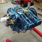
It’s been a but more than a year since my engine was built, and the protections applied at the build shop were said to be good for 12 months.  I’ve been careful not to turn the engine, and have kept it’s openings mostly plugged, but I asked the kind folks who built the engine up at Aero Sport Power what measures I should take to prolong the preservation, given that it will likely be several more months before the fires are lit.  Having procured the necessary items, I carried out their recommendation tonight:

  • Pour 3 gallons of oil into the crankcase.  They said this could be automotive oil, as it’s only there to cover and protect, not lubricate for flight.  I put in conventional (non synthetic) Valvoline.
  • Cap off the breather and exhaust stacks.  I had a plug that fit into the breather hose, and I wrapped the stacks in plastic & tape, since I don’t have any plugs that large.
  • Cap off the intake; this is already done, before I started doing any fiberglass work on the FAB & intake scoop.
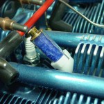
  • Insert dehydrator plugs and keep them dry.  I looked around and found some that the crystals can be taken out of and dried.  Make sure to ask that, as there are several places selling 14mm ones that are sealed, alongside the regular reusable 18mm versions.

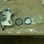
I’ve been doing final reading on brake fluid & seals, and I decided to change out the caliper O-rings, since the stock Buna-N ones will deform in the 250* range.  There have been cases of brake fires on RV’s and similar aircraft before, so many guys are replacing the 5606 fluid (flash point in the 200′s) with the more modern 83282 (flash point in the mid 400′s).  Synthetic ATF is another option, which has specs similar to that of the 83282.  It’s also become common to change out the O-rings with Viton, which is rated to 400*. The downside to Viton is it’s poor low-temperature performance (-15*).  Since I do plan/hope to fly in the winter, I found some flourosilicone O-rings at McMaster, which have the same high-temp rating as Viton, but are also rated to -75.  (They’re listed under “military specification o-rings,” p/n 8333T255)… a little pricey at $6.25 for a 2-pack, but that’s small potatoes.

The install couldn’t be easier: remove the caliper, pop out the piston, remove the old O-ring, clean up the piston & bore, lube the O-ring and insert it, then slide the piston back in place and re-assemble.  Done.

Finally, the mixture linkage has been bugging me for awhile; even with the higher hole I drilled in the quadrant lever, it wasn’t confidently hitting the stops on the fuel servo before hitting the end of the quadrant throw.  (Yes, I tried a bunch of different arm angles.)  To solve that, I pulled the mixture arm off and drilled another bolt hole a bit higher than the existing one, then reinstalled.  Works perfectly now, the stops are hit before the quadrant lever runs out of travel, and the throw matches that of the throttle lever.

Hours: 1.9 | Posted in Engine, Gear & Fairings | Comments Off
2nd April 2011

Forward cabin loose ends

More wrapup of loose ends in the cabin area, mostly dealing with the last of the electrical:

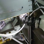
  • Installed the DB-37 connector shell and hood for the ADS-B, and tied up that bundle.
  • Installed the hood on the ARINC module connector.
  • Soldered the 3.5mm jack on the ADS-B maintenance port connector, enlarged a tooling hole in the subpanel, and installed the jack there.
  • Fabricated engine ground cables and installed between the firewall ground buss and the engine case.
  • Measured for throttle and mixture control cables.
  • Cut and installed the ducting between the vent scoops and the panel vents.  (Need to get some screen mesh to put on the vent scoop end to prevent ingress of bugs.)
  • Removed the parking brake cable from its mount, so that the mount could be removed and painted.  Realized that the ball bearing fell out of the cable mechanism; spent some time searching for it in vain.  (Hint to similarly troubled souls: ACS sells replacement balls for $2 apiece; a bag of 50 is under $5 at McMaster, and then you can lose it 49 more times.)
  • Swapped out all the screws on DB connectors for thumbscrews…much easier to work with, especially upside down under the panel.
  • Installed a snap bushing in the left subpanel rib for the pitot and AOA lines to pass through.  Ran those lines up the left vertical FW stiffener and tied in place.
  • Tidied and tied up the bundles of wire in the tunnel.
  • Cut pieces of vinyl tubing to slip over the tubing in the tunnel for anti-chafing at tiedown points.  With much contortion, tied up the fuel and brake lines in the tunnel.  Still a couple to do, and one tiewrap base where the glue is obstructing the hole; it may be possible to open it up with some safety wire.

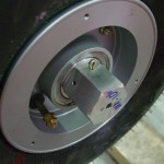
The day’s other task was attempting a redo of the nosewheel bearing.  When I installed the wheel before hanging the engine, I noted that the rotation was quite stiff.  I have the Matco axle which was supposedly designed in part to alleviate that problem.  It’s very stiff…one theory was that I didn’t manage to properly grease the bearings (they are tricky to hand-pack with the molded rubber seal).  So I bought a bearing packer cup, which did a fine job of packing it; grease squeezes out under the seal.  Re-installed, and no change.  If I tighten down the ring on the axle that’s supposed to set the preload (the instructions say to tighten it until the bearing face does not rotate with the wheel), the wheel requires what seems to me to be a lot of force to rotate.  Given the discussion around the nosewheel issues, this doesn’t seem right.  The bearing cones feel fine on inspection, too.  Anyone out there with experience installing the Matco axle that can confirm or point out where I went wrong?  For now, put it back together, knowing at least that it is well-lubricated.

Hours: 5.7 | Posted in Electrical, Gear & Fairings | Comments Off
9th January 2011

Engine hanging

Before the engine could go on, there were a couple remaining items to take care of.  First, the nose gear had to be installed, and the wheel bearings greased.  I’ve packed bearings before, but these were difficult because they have a rubber seal on one side of the bearing, so the usual “pack it in ’till it comes out the other side” didn’t work out.  I packed it in as well as I could; the glob in my hand kept getting smaller, so it must have gone somewhere, but I’m not sure it was done perfectly, so I may revisit this wheel when I repack the mains prior to flight.  I also looked at the preload adjustment on the Matco axle; you’re supposed to tighten the preload ring until the bearings remain stationary to the axle while the wheel rotates.  I was able to get them to not rotate, but the wheel is very stiff…need to do more reading on this.

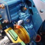
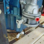
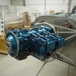
Item number two was to move the oil pressure fitting on the engine from the side port to the rear port.  I removed the fitting and the plug, and swapped them, installing the plug with EZ turn to the specified torque (which involved tracking down a copy of the Lycoming torque specs in Lycoming  publication SSP-1776).  The pressure fitting is just finger tight for the moment, until I determine if it ought to be a straight fitting instead (and if so, make one with a restrictor).  While I was monkeying with the engine, I also pre-installed the 90* fitting with the pressure tap on the fuel pump outlet.

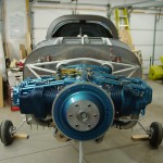
With all that done, I took another look through my pre-engine hang list, and decided it was time.  I followed the “Illustrated Guide to Engine Hanging” and the procedure was pretty straightforward.  The trickiest part was the upper left bolt, as the nut is close enough to the pushrod tube that a box-end wrench gets trapped by the bolt when fully tightened, and the hole in the engine case is such that a box-end can’t get on the nut well.  I ground down a cheap box-end wrench so it was thinner along one edge, which let me remove it after the bolt was torqued.  Getting the cotter pins in was fun as well, and required some attention during the torquing process to see that the holes ended up in an accessible orientation.  In the end, no problems with the hang, and it’s looking good.

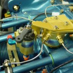
Once the engine was on, I couldn’t resist pulling out the fuel servo and test-fitting it. The AFP kit includes a nice anodized bracket/transition piece which fits between the servo and the sump, however, it is rather thick, and with it in place, the studs on the sump aren’t long enough to allow for the washer, lock washer, and nut.  In fact, they don’t even protrude through a single washer and nut.  Without the spacer in place, the throttle linkage hits the bottom of the sump, so clearly it needs to be there, and it also provides a mounting location for the control cable brackets.  I’ll have to look into the length issue.  Also need to look into how the airbox is intended to fit onto the servo; the parts are all there, but it’s not immediately obvious which way they’re all intended to go.  Lastly, I moved the throttle, mixture, and purge valve levers to the approximate locations they’ll need to be for the control cable attachments.

(Engine hang at ~1110 hours.)

Hours: 4.9 | Posted in Engine, Gear & Fairings | Comments Off
6th January 2011

Round things, and things that go ’round

More items from the pre-engine-hanging punch list tonight…

Installed the protection diode on the master contactor.  Need to order another diode for the starter contactor.

Installed the right-hand wiring passthru in the firewall, pretty much in a mirror-image location of the left one.  I found a number of builders who have put them here and said it worked well.  Their photos showed good wiring routes for everything, and it will be an ideal position for feeding the main buss wire into the Vertical Power box.  It also leaves open some real estate on the bottom of the firewall for the possibility of putting a heater box there.

Put the engine mount in place and snugged down the bolts to hold it.  Put the nose gear in and temporarily placed the bolt at the top.  I’m wondering if it would be a good idea to upgrade this to a close-tolerance bolt; I know some have tried taper pins but had a heck of a time reaming the tapered hole in the hard steel leg.

Decided to finish off the main gear legs, so hoisted the fuselage up one side at a time to adjust and drill the axle nuts for cotter pins.  The engine hoist and a double cargo strap to the gear tower worked nicely to get the wheel off the ground.  Since the gear-leg bolts are not yet torqued, it was easy to drill the top side, then pull the leg to drill the bottom hole.  After marking each hole with a drill bit, I removed the nut and ground a depression in the threads with a burr in the Dremel tool, then replaced the nut and drilled the hole.  Found this method on the forums, and it worked well to keep the axle threads from splitting and tearing up the nut threads.

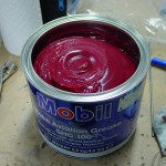
For the gear, I’m using the grease recommended by the maker of the main wheels, Mobil Aviation SHC 100, a non-clay-based synthetic grease.  The smallest quantity I could find to buy was the 4.4-lb can…that’s a lot of grease, and it’s spendy stuff too.  I’m using this because the main wheels came already packed with it, and the nose wheel isn’t packed with anything; may as well use the same stuff all around.

Still to do before engine hang: seal and install the firewall recess (which will involve removing the top skin), seal and install the wiring passthrus and brake reservoir, pack the front wheel bearings, and deal with the oil pressure fitting.  Need to look up the mix ratio for the CS1900 firewall sealant so I can mix smaller batches than the entire pint can.

Hours: 2.9 | Posted in Electrical, Gear & Fairings | Comments Off
21st November 2010

Rolling around

Freezing rain and snow on the way — tonight’s essential task was to get the main gear under the fuselage (Allison’s car needs inside).  While this may not be the absolute best way to go — adding the gear lifts the fuselage up quite a ways, meaning any work done over the side will now require a stool — I think it’s the best choice for this project, at this point, since it should let me pretty easily move the fuse around the shop between the “working” configuration and the “parking” configuration.

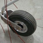
So, I bolted up the brake brackets and gear legs, omitting the wheel pant brackets for now, as I’ve read they are easy to snag and break while working around the plane.  Mounted both tires to the wheels, and put them on the legs with spacers and axle nuts, then removed the sawhorse.  I was surprised at how light the tail is in this configuration — will have to remember to be careful loading stuff, including myself, into the cabin, to avoid a nose-ground interface.  A sandbag on the aft deck should take care of that issue.  I set the tailcone on a caster-base stool, and it’s easy to wheel around the shop, so I’m hoping this will help keep progress going, and a car space open.  I’ll have to rework the shop to eliminate some boxes, in order to gain enough length for the engine & mount on the front of the fuse.

Brake flanges on gear legs Fuselage rolling on main gear

Hours: 2.0 | Posted in Gear & Fairings | Comments Off
18th November 2010

Moving on

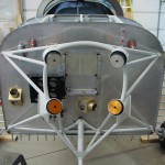
Removed the vertical and horizontal stabilizers along with the various spacers and brackets which accompany them, the rudder stops, and fuel tank attach brackets.  These all need priming, and having them off will make the winter shop configuration more manageable.
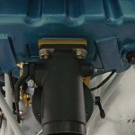
The next step is to get the nose of the fuselage off of the scaffold, since it blocks access to the firewall, which is needed to begin work there (in preparation for the engine).  The easiest way to do this, I think, is to put on the gear legs and use a rolling stool under the tail (the plane is tail-heavy without the engine up front).  To that end, I started work on assembling the gear legs by finding all the bits and pieces, and monkeying with the brake assemblies to understand how they go together.  I polished some light rust off of the axles, then reamed the 5/16″ hole for the bolt which attaches the brake flange.  With a light coat of bearing grease, the flanges went on and are now attached.  I also have the brake brackets on now, but not bolted, as I need to verify they are in the correct orientation–the C2 plan page references in the manual leaves much to be desired in this area.
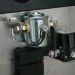
Tonight’s research project: wheel assembly.  Oh, and I need to pick up some tire talc (aka baby powder?).

Hours: 2.1 | Posted in Gear & Fairings | Comments Off