23rd January 2009

Fuel tank fabrication odds & ends

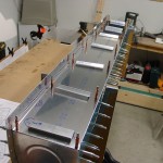
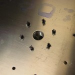
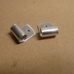
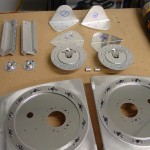
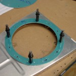
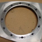
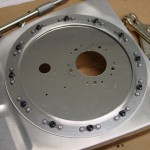
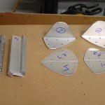
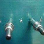
Squeezed the rivets for the right tank end rib reinforcement ring & nutplates.  Located and drilled the fuel caps and drain flanges, then fabricated and drilled the clips that hold the vent line to the fuel cap flange.

That basically wraps up the pre-sealing fabrication work for the fuel tanks.  Up next is deburr, dimple, and prime the external brackets; then it’s time to seal these puppies up.

Hours: 1.6 | Posted in Fuel Tanks | Comments Off

19th January 2009

Tank end ribs & access plates

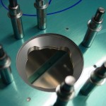
Cut the access holes in the fuel tank end ribs using the Dremel tool with a circle-cutting guide.  The centering pin on the device fit perfectly into a #30 hole, so I marked the center of the circle to be cut and went to town.  Cleaned up and smoothed the edges of the holes with a curved file, then used the 2″ scotchbrite wheel in the drill press to finish it off.  Located and drilled the cover plate, then the reinforcement ring.  Drilled for the nutplates holes, dimpled, countersunk, and deburred everything.  The left side is riveted together with the nutplates, and the right is clecoed, waiting for rivets.  A simple little fabrication exercise for the evening.  These assemblies go together quickly when you don’t have to worry about prep & priming!  (The innards of the fuel tanks remain unprimed, to avoid any reactions between the coatings and the fuel.)

Hours: 2.4 | Posted in Fuel Tanks | Comments Off

18th January 2009

Fuel tank fabrication

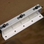
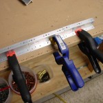
Lots of hacksaw, sander, and scotchbrite wheel work…  Fabricated the inboard tank attach brackets; match-drilled them to the tanks.  Fabricated and drilled the inboard and outboard reinforcement plates–used 5 rivet locations per plate.  Drilled and countersunk the rivet holes on the spars that hold the inboard tank attach platenuts.  Deburred all holes and fabricated pieces, plus the Z-brackets for both tanks.

My goal for this week is to be better about doing some short evening sessions; even though I’m booked with other commitments for a minimum of two nights each week, I think that would help create a feeling of progress, which in itself is a motivator.  Last week was so cold (-20 lows, -5 to +5 highs for several days running) that I was reluctant to heat the shop for short sessions, plus the rest of life was busy.  There’s a half page of fiddly stuff now to get the tanks ready to seal: fuel caps, tank drains, dimpling, platenuts and the like (plus priming some of the external small pieces), which ought to make fine fodder for short sessions.  Here’s to progress!

Hours: 2.8 | Posted in Fuel Tanks | Comments Off

11th January 2009

Fuel tanks

Repeated the work done yesterday on the left tank on the right: reversed the end ribs that were put on the wrong ends, drilling the baffle and brackets, fitting to the wing, back-drilling the brackets to the spar, splice strip, and checking for wing twist.  This wing wasn’t perfect (as the left wing was), but only reads 2/32″ difference from end to end, which is within the allowable spec given by Van’s (3/32″).

Pulled both tanks and match-drilled all the holes–lots of cleco moving.  Countersunk the skin-to-baffle holes; this allows the baffle to slide in to a flat surface during tank sealing, rather than dimpling the skin and baffle.  Drilled the tank-to-spar screw holes to #19, using the battery drill as it turns slower than the air drill, and the bit was grabbing with the air drill.  Worked well, except that the battery drill weighs a ton compared to the air drill, making for a tired arm.  (I wouldn’t mind having one of the 1/4″ Sioux drills for all the match-drilling, but with two 3/8″ air drills and a battery drill, don’t really need it…)

Pulled of the Z-brackets and baffle by drilling out the temporary pop rivets–the stems broken off high were not an issue, as they pushed out very easily with a small punch.  Deburred the drilled holes, and proceeded to drill the nutplate rivet holes by using bolts stacked with washers and nutplates as a drill guide.  Countersinking the nutplate attach holes on the aft side is helped by clamping a couple of the other brackets in a row, allowing the foot of the countersink cage to have support, making accurate countersinks on the upper- and lowermost holes.  I did goof and drill nutplate rivet holes on the #1 brackets as well, which are unnecessary, since those bolts go from the tank side into nutplates riveted on the spar.  I don’t believe that will be a problem, and the holes could be countersunk and filled with short rivets if needed (I deburred them, but left them un-countersunk, so as to not remove more material).

The next couple steps require fabrication: the reinforcement plates have to be trimmed down to match the curve of the nose of the tank, and the tank attach angles also need to be trimmed from a raw piece of heavy angle.  This is stuff where a bandsaw would be a welcome tool to have.  The hacksaw I have is a crude tool, and never wants to cut a straight line.  I might try and see how the recip saw would work for roughing out the heavy angle, then finish to size with the vixen file.  Also need to pick up a fly cutter for cutting the access holes in the tank end ribs, though I’m not completely certain how well that will work with the drill press at hand; I don’t recall what the lowest RPM setting is.  I suppose I also need to think about a flaring tool for the AN fittings internal to the tank (pickup & vent; I believe the pre-fab screened pickups I bought are pre-flared, but the vent line, which is fabbed from a roll of tubing, is not).

Hours: 6.6 | Posted in Fuel Tanks | Comments Off

10th January 2009

Fuel tank assembly

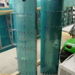
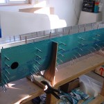
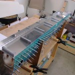
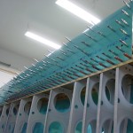
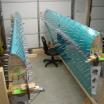
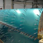
Fabrication & prep work begins on the fuel tanks with the same procedure that builds the leading edge: getting the ribs placed into the skin.  I continued to use the bar-clamp method, which made it relatively easy, and the results were good.  Assembled the ribs & skins for both left & right tanks, then fabricated and installed the stiffeners for the bottom side.  I got ahead of myself and fabricated two left versions of the inboard stiffener (it’s shorter), so I fabricated a new one out of a piece from the “trim bundle” that came with the empennage kit.  It probably doesn’t make any difference if that one would have been backwards, but wanted to have it right in case it might interfere with the fuel level float.
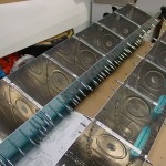
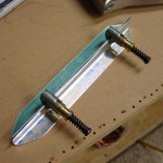
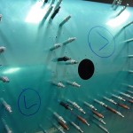
Pulled the baffles for the tanks and continued the left tank by clecoing the baffle into the assembly, then laying out the Z-brackets and marking them for order.  Used the drill guides to put the center holes on the flanges of the brackets, and enlarged the rear holes to 3/16″.  Took the baffle back off the tank and back-drilled the rest of the holes in the baffle side of the brackets.  Drilled the baffle to the ribs as well, then deburred baffle & brackets.
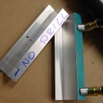
In reinstalling the baffle and brackets on the tank, I discovered that I had the tank end ribs installed backwards, so had to swap those inboard for outboard before assembling the baffle.  Also had to grind down the nose of my pop-rivet puller to fit into the brackets and install the soft pop rivets used to temporarily attach the brackets.  All the stems of the pop rivets broke above the level of the rivet head; a common problem, and nothing that’s cause for worry (especially since these are temp rivets), but I wonder how much that will complicate the removal of these temporary rivets when they need to be drilled off to get back inside the tank…
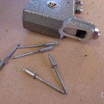
Clecoed the baffle to the skin in every other hole per instructions…all the clecoes must double the weight of the tank!  Installed it on the spar and saw a gap similar to the one I had on the LE…sigh!  Unexpected, since I had made measurements as each rib was installed, and all looked good.  But, closer inspection showed that the problem was the cleco “tongues”, which weren’t clearing the tallest portion of the upper spar bar, and so holding the tank up.  Removing the clecoes from that section of tank allowed it to sit down nicely, and all fit well.  Clecoed into every platenut hole top & bottom, and the center drilled holes in the Z-brackets.  Back-drilled the 3/16″ holes from the spar into the brackets, and drilled the splice strip (using a #18 drill, according to the Standard Aircraft Handbook, which is old but has a great hardware reference).
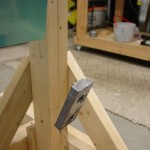
Wrapping up for the night, I made some impromptu plumb bobs with the lead weights for the elevators, with fishing line skip-knotted around them.  Attached to clecoes in the ends of the main spar, this allows you to measure for twist in the wing, by measuring the distance to the rear spar from the plumb line.  4 1/32″ on both ends…no twist.  (Plans specify allowable twist of 3/32″.)  Ended on that high note, with a good day of work behind.
Also realizing that I need to take action on things like ordering Proseal, leading edge lights, and pitot tube, so those things can be ready for installation.  Also need to check and see if Trutrak servo brackets are available for pre-installation; I believe they were made unavailable when the Dynon autopilot came out, as people were ordering the TT brackets to use with Dynon servos, but I don’t know if that’s changed.  I would like to have the plane ready for AP installation, but don’t want to buy the servos yet for reasons of funding.
Hours: 6.4 | Posted in Fuel Tanks | Comments Off