Fuel tank assembly
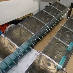
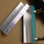
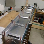
Hours: 6.4 | Posted in Fuel TanksFabrication & prep work begins on the fuel tanks with the same procedure that builds the leading edge: getting the ribs placed into the skin. I continued to use the bar-clamp method, which made it relatively easy, and the results were good. Assembled the ribs & skins for both left & right tanks, then fabricated and installed the stiffeners for the bottom side. I got ahead of myself and fabricated two left versions of the inboard stiffener (it’s shorter), so I fabricated a new one out of a piece from the “trim bundle” that came with the empennage kit. It probably doesn’t make any difference if that one would have been backwards, but wanted to have it right in case it might interfere with the fuel level float.
Pulled the baffles for the tanks and continued the left tank by clecoing the baffle into the assembly, then laying out the Z-brackets and marking them for order. Used the drill guides to put the center holes on the flanges of the brackets, and enlarged the rear holes to 3/16″. Took the baffle back off the tank and back-drilled the rest of the holes in the baffle side of the brackets. Drilled the baffle to the ribs as well, then deburred baffle & brackets.
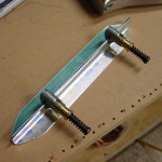
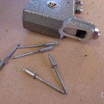
In reinstalling the baffle and brackets on the tank, I discovered that I had the tank end ribs installed backwards, so had to swap those inboard for outboard before assembling the baffle. Also had to grind down the nose of my pop-rivet puller to fit into the brackets and install the soft pop rivets used to temporarily attach the brackets. All the stems of the pop rivets broke above the level of the rivet head; a common problem, and nothing that’s cause for worry (especially since these are temp rivets), but I wonder how much that will complicate the removal of these temporary rivets when they need to be drilled off to get back inside the tank…
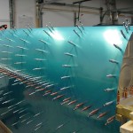
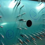
Clecoed the baffle to the skin in every other hole per instructions…all the clecoes must double the weight of the tank! Installed it on the spar and saw a gap similar to the one I had on the LE…sigh! Unexpected, since I had made measurements as each rib was installed, and all looked good. But, closer inspection showed that the problem was the cleco “tongues”, which weren’t clearing the tallest portion of the upper spar bar, and so holding the tank up. Removing the clecoes from that section of tank allowed it to sit down nicely, and all fit well. Clecoed into every platenut hole top & bottom, and the center drilled holes in the Z-brackets. Back-drilled the 3/16″ holes from the spar into the brackets, and drilled the splice strip (using a #18 drill, according to the Standard Aircraft Handbook, which is old but has a great hardware reference).
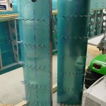
Wrapping up for the night, I made some impromptu plumb bobs with the lead weights for the elevators, with fishing line skip-knotted around them. Attached to clecoes in the ends of the main spar, this allows you to measure for twist in the wing, by measuring the distance to the rear spar from the plumb line. 4 1/32″ on both ends…no twist. (Plans specify allowable twist of 3/32″.) Ended on that high note, with a good day of work behind.
Also realizing that I need to take action on things like ordering Proseal, leading edge lights, and pitot tube, so those things can be ready for installation. Also need to check and see if Trutrak servo brackets are available for pre-installation; I believe they were made unavailable when the Dynon autopilot came out, as people were ordering the TT brackets to use with Dynon servos, but I don’t know if that’s changed. I would like to have the plane ready for AP installation, but don’t want to buy the servos yet for reasons of funding.
