26th July 2011

FWF loose ends

Worked on more engine-related stuff tonight:

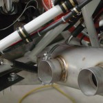
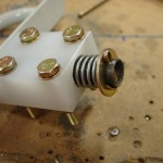
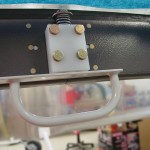
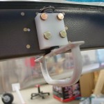
  • Finished up making and installing the exhaust hangers
  • Torqued and sealed the case bolts where the hangers bolt to
  • Test fit the lower cowl to check for exhaust clearance, and adjusted the left side a bit to gain more space
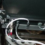
  • Rerouted the starter cable to get more clearance from one of the hanger tubes
  • Added an adel clamp to the purge return line alongside the battery box
  • Installed the hose portion of the breather; need to get some large alum. tubing for the lower portion
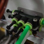
  • Drilled a hole for the fuel pump vent exit, bent a piece of -4 tube, and secured it (at least temporarily) to the engine mount
  • Cut a slot in the camlok strips to allow for insertion of the vertical hinge pins on the lower cowl


Hours: 3.6 | Posted in Engine | Comments Off

24th July 2011

Working the list

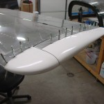
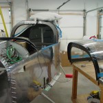
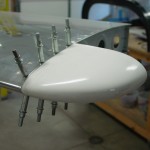
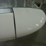
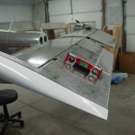
Started out by giving more attention to the HS/VS tips (the elevator/rudder tips don’t require so much work, and I’m glad for it).  Sanded the filler layer of micro I added yesterday, and got things looking relatively decent.  Spent some time reading on what the process is from here; it looks like there should be an epoxy sealcoat or three over the microed area, then a primer, and possibly another primer after that.  I’m reading much of what DanH has written over at VAF, and have found the specs for the PPG coatings used by many of the folks; have to see if there is a local supplier, or if it’ll be a mail-order operation.  DPLF is the basic primer, and K36 is the high-build primer/surfacer.  The finishing steps, as I understand them, are to brush or roll 3 layers of straight epoxy, then sand, shoot DPLF, sand/fill if necessary, then a light coat of DPLF and a coat or two of K36.  I don’t know if the K36 step is needed at this point, or if that’s something that’ll happen at paint prep time.  After sanding them up, I added a fillet of flox to the inside of each tip, to strengthen up the joint at the back.  Hopefully these will be done soon…

Next I tackled the pre-installation for the SD-8 backup alternator/dynamo.  I’ve installed the relay and capacitor, but haven’t bought the regulator or dynamo to save the $500 for the moment.  This is purely a backup device, so I don’t need it to get flying, but want to add it eventually.  I drew up a full-size paper mockup of the regulator so I could locate nutplates to secure it, and installed those.  Then, I installed all the wiring, and ran the lines which run to the regulator to a CPC connector mounted below where the regulator will go.  When I get the regulator, I’ll put a mating CPC on it, and it’ll be a simple matter of bolt in and plug in.  Also ran a loop of wire FWF and secured the excess length to the wire bundle along the upper engine mount tube, where it’ll stay until the installation of the dynamo.


Started on the installation of exhaust mounts.  Tightening down the bolts on the ball joints to the specified 2-threads caused them to become rather tight, so I may need one length longer bolts there — not sure how tight or loose it’s supposed to be, but the install guide does say that it’s important they be able to flex, and recommends lubricating them regularly.  Got the right side hangers fit, and the left side marked and cut, before quitting time.

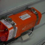
And, stuck the biennial registration sticker on the ELT.

Hours: 5.4 | Posted in Electrical, Engine, Wing & Tail Joins | Comments Off

16th July 2011

A few tips…

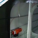
ELT batteries came in the mail this morning, so the first item on the list was installing them.  The lithium batteries are good for 10 years, according to the ELT manual, but the expiration date on the batteries is March 2020, so I’ll enter that as the replacement date.  With the batteries in and everything back together, I armed the ELT and pushed the button to initiate the self-test.  One beep came from the audio alert, which is supposed to indicate that the system has passed all its checks and is good to go.  Disarmed the unit.  Also, reached up into the tail and tightened down the nut on the ELT antenna.

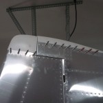
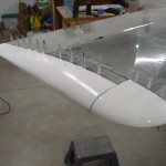
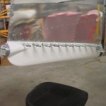
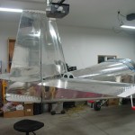
Spent the rest of the day working on the empennage.  Lots of fitting, trimming, filing, and sanding of fiberglass tips.  The vibrating saw I bought for the canopy work also works very nicely on fiberglass, so I’m using that to do the rough trims, then following up with a flat file, a triangular file, a half-round file, and a 2′ 1×3 with sandpaper glued to it.  (Drywall corner bead adhesive works really well to stick sandpaper to a board.)  And, the heat gun to warm up a couple recalcitrant parts so they could be shaped.  Finished basic fitting of all the empennage tips, though there’s still plenty to do.  The VS tip needs to have some height added to it to match the rudder, and the left elevator tip has a dip molded into it that will probably need filler.  Plus, there’s the closeouts of the VS and HS tips with foam/fiberglass/micro/shaping them to match the control surfaces with acceptable gaps.

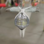
The rudder bottom was the most time-consuming, since it needed lots of trimming to fit around the rudder horn.  I initially trimmed to the scribe lines, and they were close, but not quite.  I have a bit much of a gap under one side rudder horn (oh well), and the other side needed to be sanded down at a taper quite a ways more before the centerline of the tip was in line with the trailing edge.  Once it was fit, I proceeded to fit the aft nav/strobe, using rivnuts to mount it.  Wired it up, adding the local ground called out in the new version of the recommended wiring diagram, and flipped the switch.  Worked well, though the nav light draws so little current that the VP-X’s no-current fault indicator kept tripping it offline, so I disabled that for the nav light circuit.  The strobe draws enough current that it keeps the strobe circuit from faulting; once the other 2 nav lights are connected, I can try re-enabling it on that circuit.

Hours: 7.8 | Posted in Electrical, Wing & Tail Joins | Comments Off

13th July 2011

Odds without ends

From the “I don’t really feel like going out to the shop but I need to do something to keep moving” file…

Removed the -14 adel clamps from the main vertical wiring trunk, and installed -15 clamps, which are large enough to contain the few wires that wouldn’t fit in the smaller ones that had been originally installed.

Terminated the boost pump power & ground into a 2-pin molex connector to mate with the one I had previously installed on the pump leads.  Test fit and tested that the pump powered up.

Wiped off the rest of the fiberglass tips for the empennage, and traced the initial trim lines with a black sharpie.

Hours: 1.1 | Posted in Electrical, Wing & Tail Joins | Comments Off

11th July 2011

Couple little things

Installed the RJ-11 connectors on the ELT remote cable, and plugged it in on both ends.  The batteries I ordered shipped today, so when those arrive, a test will be possible to verify that it’s working correctly, then the ELT can be deemed fully installed.

Made up a couple 2″ test links for the rudder pedal-cable connection out of scrap alum, to test that length before committing to cutting the steel pieces.  Seems to be alright, one thing I noticed is that at full travel, the swaged end of the cable hits the first snap bushing behind the pedals.  Not sure what that’s about, or if it’s normal, but the thing setting that location is the length of cable from the rudder horn.

Hours: 1.2 | Posted in Electrical, Wing & Tail Joins | Comments Off

10th July 2011

Looks like an airplane

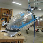
Having picked up some different adhesives last night for the glareshield covering, the first item on today’s agenda was the finished that job.  I had stupidly gotten ahead of myself and removed the inside plastic covering yesterday, in order to be able to work better down in the tight corners at the front.  So, I taped up a bunch of newspaper on the inside of the canopy, to mask the bubble against any overspray.  Feeling sufficiently masked, I sprayed some Super 77 on the glareshield, and a coating on the backing of the fabric, waited the appointed time, and stuck them together.  I did have some troubles with the fabric sticking to the newspaper in the corners, duh…I knew there was a reason I had planned to not put adhesive on the fabric.  Sigh.  In the end, though, it stuck down well, and laid nicely.  It appears that even with my newspaper mask, a couple areas of plexi got a light fogging of overspray, aargh.  I’ve read through the VAF threads about canopy oversprays & cleaning, and sent off for some supplies from Spruce.  This too shall pass, with some elbow grease.

With the fabric in place, I inserted the snap bushing and GPS wire…looking good.

Next task was soldering the ELT connector, so I climbed into the baggage compartment again with tools & supplies.  Easy enough, then I made the LED test tool specified in the manual, which lets you see if the GPS signal is being received by the ELT.  It was, so I buttoned that install up; if I can remember to bring my modular crimpers home from work tomorrow, I’ll be able to put a bow on the ELT installation and cross that off the list.  I also ordered the batteries for the remote units today, having failed to find them at 3 local stores that carry camera batteries.

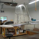
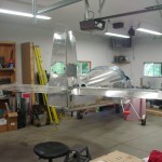
I decided that for whatever reason it was time to set the lengths of the control system pushrods, so I moved things around enough to fit the empennage.  I also primed some spacers and things that needed priming, part related to the empennage attachment.  Bolted on the HS and mounted the elevators.  Decided to fit the HS tips, so I had to do a little bit of trimming, and cleaned up the stepped edge to a nice crisp line with files, before positioning and drilling.  A couple trips in and out of the tailcone had the pushrods adjusted to get full stop-to-stop deflection of the elevators, hitting the travel stops at the elevator end rather than the control column end.  I measured the travel of the elevators to verify it was within spec, and it was.

Since I had the elevators rigged up, I figured I would connect the trim servo and configure it in the VP-X and EFIS.  That was a simple proposition, but I found that the pins for the up/down trim commands into the VP-X needed to be reversed opposite of what’s indicated on the load planning document (ie, 18 down, 19 up).  Once the correct motor polarity was set, the buttons in the software caused the servo to move correctly (“move up” moved the tab down for nose up trim), but the stick switch was running opposite that.  I tested the pins to be sure that I hadn’t reversed them accidentally — I hadn’t, the one marked up was indeed grounded when the up trim switch was pushed.  Swapping the pins at the input of the VP-X allowed it to run as expected.  Not sure what’s going on here, and I’ll be sure to double-check this system later to be sure it’s functioning properly, that I didn’t just have a bad brain day and set it up backwards.  Once it was running right, I measured the travel of the tab to be in-spec, as well.

Finally, mounted the VS and rudder.  Connected the rudder cables to the rudder horn.  Looks like I’ll need the connecting links to be around 2″ long — now, where to find the steel bars that they’re made from…  The rest of the empennage tips will get fitted next, I think; a little fiberglassing practice to close them out, then those surfaces can come back off for storage until final assembly.

Hours: 7 | Posted in Electrical, Wing & Tail Joins | Comments Off

9th July 2011

Canopy miscellany

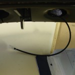
Terminated the lighting wires that emerge from the underside of the canopy structure in a mating plug to the one installed on the subpanel the other day, and covered the loop with nylon sleeving for chafe protection.  Drilled a hole in the center of the glareshield to pass the GPS cable through.  Unpinned the  puck GPS cable from the DB9 connector, so it can be passed through the canopy hole when ready, and put a snap bushing on the cable. Two cables will come from the canopy, the panel floodlight and the GPS, both of which have a disconnect on the subpanel.

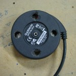
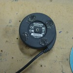
Also removed the magnets from the bottom of the GPS puck, and filled the holes with RTV to re-seal the casing, since with the magnets removed, you can see the sensor board and wires inside the unit.  Temporarily reconnected the GPS to the EFIS to verify that nothing was damaged during magnet removal; all appears functional.

Soldered a 3.5mm jack on the end of the cable that’s connected to the passenger phones line of the audio panel, and installed that jack into the bottom flange of the instrument panel, over on the passenger side.  I wired this up to provide a convenient place to tap into the intercom/radio audio with an audio or video recorder.  All audio wiring is now complete.

Worked with the block of black Delrin I ordered to fabricate and install the canopy closure guides.  The idea is that these low-friction guideblocks will capture the latch fingers as the canopy lowers, then align them properly with the holes they must pass through.  By providing a mechanical means for alignment (rather than relying on a human to guide it), the hope is that the possibility of cracked canopy corners or beat-up latch plates will be reduced.  This is a fairly common addition, it seems.

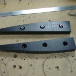
I started with a block of Delrin from McMaster, 1/2″ thick, 1″ wide, and 12″ long.  Measured and marked some guide lines, cut on the bandsaw, shaped on the disc sander, and cleaned up with a razor blade and scotchbrite, ending up with a pair of symmetrical guide blocks that look decent and should do the job.  To secure them, I decided to use #6 hex-head screws.  I drilled the holes, 3 per block, with #27 for the screws, then counterbored a 3/8″ flat-bottomed hole (start with a regular 3/8″, finish with the forstner bit again) about halfway through the block, then pressed in a 3/8″ OD  #6 black stainless washer, which will spread out the screw force, but you can’t tell it’s in there, since the color matches that of the Delrin.  Used the blocks to match-drill the rollbar, then tapped the holes, since getting nuts and wrenches that far up in the hollow rollbar would be nearly impossible.  These blocks are not structural, and they’re plenty solid with the tapped holes.  I think the install turned out well, though I’ll have to wait awhile until canopy installation to see how they actually work.

Used some newspaper taped together to make a pattern for the glareshield covering, then transferred that pattern to the material, and cut.  I’m using a big piece of industrial fabric which is the loop-side of hook-and-loop fasteners.  Essentially, it’s a giant piece of female Velcro.  The GPS puck will be fastened to it by sticking dots of male velcro on the bottom, and any other items that would be handily secured there can be fastened in the same way: wrap a strip around pens, flashlights, and so on.  I left the aft end of the cut fabric long, then fit the piece to the forward edge curve (the inside of the canopy bubble), and wrapped the aft end over the glareshield edge.  Using the pinch welt I got from Classic Aero, I secured the aft edge in place, then cut with a razor blade along the edge of the pinch welt on the bottom side to remove the excess length.  Poked a  hole matching the hole drilled in the glareshield earlier, where the snap bushing will go.  Finally, I flipped the entire piece out, over the pinch welt.  I’ll find some adhesive material to apply to the glareshield, then roll the fabric down over the top of it, to bond it securely in place.

Hours: 5.0 | Posted in Canopy & Frame, Electrical | Comments Off

8th July 2011

Small victories

Some days, checking off little tasks can give a good feeling…today was one of those days.  Not much got done, really, but it was nice to call a couple things finished.

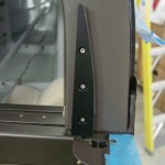
The major victory for today was the installation of the secondary canopy latch with spring modification.  I’ve mentioned a bit about this before; today I headed to the hardware store to dig around and come up with some springs that would work.  A found a 5/8″ by 1 9/16″ compression spring that was a perfect slip fit on the 1/2″ shaft of the latch, and had a good strong spring force.  To accommodate the length of the spring (it needs to be long enough to allow the latch to pull down far enough to clear the canopy frame), I chose not to cut the UHMW block down to capture only 2 of the mounting bolts, but rather to counterbore the block for the spring.  Since the 1/2″ hole is already drilled, I used a Unibit to enlarge it to the 5/8″ step, followed by a 5/8″ forstner bit in the drill press to bore the hole to the required depth (I went almost 3/4″ here).  Cleaned up the hole so the shaft slid freely, installed the spring into the hole, and capped with washer and cotter pin.  Pretty slick, I think.  I bolted the latch to the canopy frame, with the latch block spaced out from the frame by placing an AN960 washer on each mounting bolt, between block and frame.  This provided just enough space that the washer and cotter pin have clearance from the frame.  I did find a smaller diameter piece that could be used in place of the washer (sold as a 1/2″ ID x 1/8″ spacer), but the head of the cotter pin still needed clearance.  It’s easy enough to change if needed, but I don’t forsee a need to replace it; the latch arm has plenty of reach to the aft side of the canopy frame, to engage the rear window bow.

Number two: installed a newly-purchased screw to complete the installation of the pitot-static manifolds.

Number three: riveted in the magnetometer mount, and mounted the EFIS 1 magnetometer.  Also slid the elevator pushrod into the tailcone.

And, finally cleaned up the shop, including the massive nest of short wire bits that had collected on the bench…

Hours: 2.5 | Posted in Canopy & Frame, Electrical, Plumbing | Comments Off

7th July 2011

Tailcone camping

Received a couple supply orders this morning, from SteinAir and McMaster, so parts were on hand to complete a few tasks.

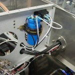
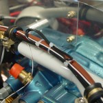
Installed the intake gaskets and bolted the fuel servo and spacer/bracket to the sump.  I bought some all-metal steel locknuts in 5/16-18, which is the thread on the long studs AeroSport sent to me.  I’ve installed the standard-height ones, but even with a thin washer, the threads are only flush with the bottom of the nut, rather than the usual 1-or-2-thread protrusion we want (though they do appear to be fully engaged; there’s just no excess).  I installed them for now, torqued and sealed, but will ask around to see if this is a real problem; if so, whether using shorter nuts (which I also bought) would be acceptable here, or if I’ll need to locate and install longer intake studs (ugh).  In other FWF news, torqued the engine mount bolts and installed cotter pins.
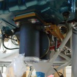
Installed the quick-connect fittings on EFIS 1, into which were installed the pitot and static tubes.  Blowing lightly in the pitot line at the wing root caused the airspeed to come alive, and capping the tube off cause it to hold steady, so the system within the fuselage appears to be tight.  Sucking lightly on a static port indicated a climb, so that’s good too, though that one isn’t guaranteed leak-free, as I wasn’t able to plug the opposite port and hold suction; that test will come later.
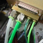
Moving toward finishing the ELT install, I drilled a hole in the aft top skin for the antenna, and fabricated a circular doubler to go inside, per the installation guide.  Routed a coax from the ELT to the antenna, secured and terminated.  Hint: a BNC connector doesn’t fit through the 1/2″ hole for the antenna, and if you install it with the coax pulled to the outside because it’s easier, you’ll have to cut it off and do it again, the hard way…don’t ask how I know.  Routed and secured most of the wiring around the ELT itself, though the wiring is not done yet.  Some fiddly soldering on a 4-pin DIN needs to be done to hook up the power and GPS signal (why they chose that awful connector, I don’t know…).  And, I need to terminate the RJ-11 ends, and of course my RJ crimper is in my toolbag at the office.
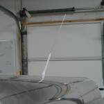
In the same area, installed a nutsert for the APRS box, and secured that along with it’s wiring.  Placed a couple ziptie bases along the wire run to the RS-232 service port and status indicator light and secured those wires, as well.  Still haven’t seen any pings from the APRS show up on the internet, though that’s not surprising as it’s been in the garage the entire time.  I might push it out someday and see if it’ll ping, but with the bottom-mounted antenna, I don’t really expect to see anything until she’s airborne.
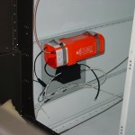
And as long as I was working in the tailcone, I finished securing the wires that run along the floor, including the addition of a few ziptie bases.  Also removed the test-fit magnetometer mount, deburred and primed it so it can be riveted in place.  I see at least a couple more trips into the tailcone (mag/mount install, finish the ELT, install the elevator pushrod) in my future, but hopefully I’ll be done with that soon, at least for awhile.  Once you’ve got camp set up in there, it’s not so bad, but getting in and out is a bear…and even more fun when you get yourself inserted and then realize the tool you need is still on the bench.
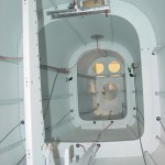
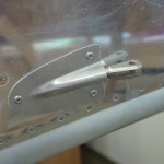
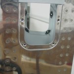
In keeping with the tailcone theme, but on the outside, I installed the rudder cable fairings that were prepped yeterday.  The night’s last act was to install the nutplates on the elevator horn inspection holes, then prep & prime the cover plates.
Checked the FAA registry tonight and saw that my N number is now showing as assigned, with the proper details of my airplane.  So, it appears my registration has been received.  I’ll laugh if the state tax people call up in the middle of the current government shutdown to ask for their pound of flesh…
Hours: 5.2 | Posted in Aft Fuselage, Electrical, Engine | Comments Off

5th July 2011

Little things

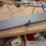
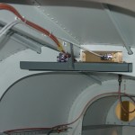
Just a bit of time in the shop after working 9 hours during the day on other things…what vacation?  Riveted in the panel brace, reinstalled EFIS 1 and connected the AOA tubing, mounted the ELT bracket, and clipped some wireties from a previous session, along with the usual staring at the project to see what’s next.

Hours: 1.6 | Posted in Cabin & Interior, Electrical | Comments Off