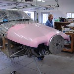
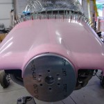
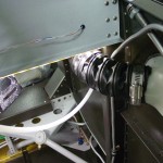
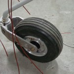
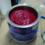
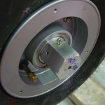
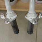
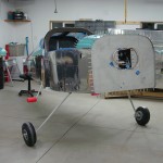
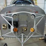
Before the engine could go on, there were a couple remaining items to take care of. First, the nose gear had to be installed, and the wheel bearings greased. I’ve packed bearings before, but these were difficult because they have a rubber seal on one side of the bearing, so the usual “pack it in ’till it comes out the other side” didn’t work out. I packed it in as well as I could; the glob in my hand kept getting smaller, so it must have gone somewhere, but I’m not sure it was done perfectly, so I may revisit this wheel when I repack the mains prior to flight. I also looked at the preload adjustment on the Matco axle; you’re supposed to tighten the preload ring until the bearings remain stationary to the axle while the wheel rotates. I was able to get them to not rotate, but the wheel is very stiff…need to do more reading on this.
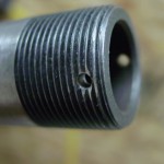
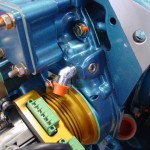
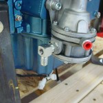
Item number two was to move the oil pressure fitting on the engine from the side port to the rear port. I removed the fitting and the plug, and swapped them, installing the plug with EZ turn to the specified torque (which involved tracking down a copy of the Lycoming torque specs in Lycoming publication SSP-1776). The pressure fitting is just finger tight for the moment, until I determine if it ought to be a straight fitting instead (and if so, make one with a restrictor). While I was monkeying with the engine, I also pre-installed the 90* fitting with the pressure tap on the fuel pump outlet.
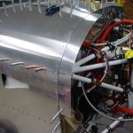
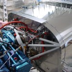
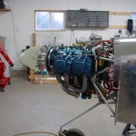
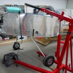
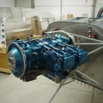
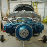
With all that done, I took another look through my pre-engine hang list, and decided it was time. I followed the “Illustrated Guide to Engine Hanging” and the procedure was pretty straightforward. The trickiest part was the upper left bolt, as the nut is close enough to the pushrod tube that a box-end wrench gets trapped by the bolt when fully tightened, and the hole in the engine case is such that a box-end can’t get on the nut well. I ground down a cheap box-end wrench so it was thinner along one edge, which let me remove it after the bolt was torqued. Getting the cotter pins in was fun as well, and required some attention during the torquing process to see that the holes ended up in an accessible orientation. In the end, no problems with the hang, and it’s looking good.
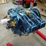
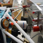
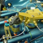
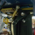
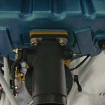
Once the engine was on, I couldn’t resist pulling out the fuel servo and test-fitting it. The AFP kit includes a nice anodized bracket/transition piece which fits between the servo and the sump, however, it is rather thick, and with it in place, the studs on the sump aren’t long enough to allow for the washer, lock washer, and nut. In fact, they don’t even protrude through a single washer and nut. Without the spacer in place, the throttle linkage hits the bottom of the sump, so clearly it needs to be there, and it also provides a mounting location for the control cable brackets. I’ll have to look into the length issue. Also need to look into how the airbox is intended to fit onto the servo; the parts are all there, but it’s not immediately obvious which way they’re all intended to go. Lastly, I moved the throttle, mixture, and purge valve levers to the approximate locations they’ll need to be for the control cable attachments.
(Engine hang at ~1110 hours.)
