12th April 2011

Oil cooler test

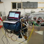
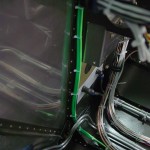
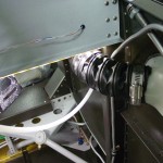
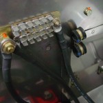
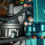
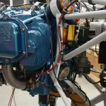
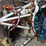
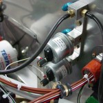
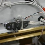
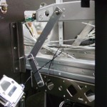
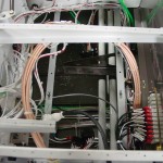
I wanted to get the order put in for all the FWF hoses at once, and to do so, I needed to identify what hoses were needed for the oil cooler hookup.  This, in turn, required test-fitting the aft left portion of the engine baffles.  The good news is that I was able to figure out what hose lengths would work, and I’ve sent that off to the guy who’ll be making the hoses.  I also determined that the hose routing should work with the wire runs and such I’ve already mounted.  I did move one adel clamp to provide some additional clearance at the lower corner of the cooler.

Also received the package from Van’s today with the AeroLED lights — these things are bright!

Hours: 1.5 | Posted in Engine | Comments Off

11th April 2011

APRS Tracker

My APRS transmitter from Byonics arrived today (along with an oil cooler and spark plugs from Spruce), so I thought that would be a simple and satisfying installation.  First, I opened up the tracker and wired a short piece of 22-3 to the internal LED, bringing it out through a small hole in the case.  A 3-pin Molex went on the end–this is to drive a bicolor LED like the one built into the tracker, but external, since I will have the tracker mounted behind the baggage bulkhead.  Having installed a TinyTrak in my car, I know it’s handy to have the status lights to see what the tracker is doing.  With the external LED plug wired, I closed the case back up and proceeded with the installation on the plane.

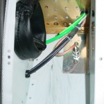
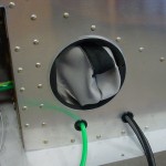
I put a pair of small holes in the baggage bulkhead, far enough to the side that they won’t interfere with the corrugated wall panel.  The top hole received the bicolor LED; it indicates green for GPS status (flashing means it’s receiving data, solid indicates a valid fix), and red to indicate it is transmitting a position packet.  The lower hole is occupied by a 3.5mm TRS jack, similar to the ones I’ve used in several other places for RS-232 service ports.  This one is a bit different, since the other (Pmags and ADS-B) are dedicated serial ports on the devices, whereas the tracker also receives its GPS signal via this port.  So, a normalling jack is used here — when there is no plug inserted, the GPS signal is fed to the tracker.  Inserting a plug breaks the GPS connection, and connects the tracker’s input and output to the computer.

I could have put the LED on the panel, but a) it’s not at all a critical item, b) the flashing light could be distracting, especially at night, c) that would require another wire through the spar, and d) it’s still readily visible by looking over my shoulder.  Both the LED and the port are easily accessible for servicing the tracker and checking it’s operation, while being completely out of the way.

Wired the tracker to power, too, and enabled that pin on the VP-X.  Terminated the coax from the NMO mount with an SMA connector, hooked that up and flipped the switch.  The tracker booted right up, so I powered the GPS and got a solid green light.  Good to go.  The service port is functional, and I programmed the tracker config and grabbed my handheld scanner to verify that it is transmitting.  None of the packets hit the internet, which doesn’t surprise me at all since it’s on the bottom of the fuselage (which makes sense in the air), and inside the shop.

Hours: 2.5 | Posted in Electrical | Comments Off

10th April 2011

Random pieces

Long week with no work on the project; the busy season has begun at the office.  Some positive news on the financial picture front this week though, so I at least ordered a bunch of pieces that I’ve been holding off on, for upcoming installation (lights, exhaust, APRS stuff, ELT, oil cooler, etc).

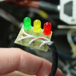
Got a few things done and half-done today; starting off with the wiring for the pitot indicator.  I bought my Gretz pitot secondhand, and it didn’t include the indicator board, since the previous owner had installed it in his plane.  No problem, it’s just a few LED’s with appropriate resistors, but I hadn’t yet taken the time to measure the voltage, find the right resistors, and build the board.  I used a chunk from a leftover piece of prototyping board, trimmed to fit the necessary components.  I also put a 4-pin Molex connector on it, for ease of connection (the soldering could happen on the bench, rather than in the plane) and service.  A matching connector on the wire behind the panel, and we’re in business.  I connected up the pitot for testing, and rolled the wing cart over to plug into the fuselage.  Power on, and everything looks good: the lights indicate as they should, the heater cycles, and the tube tip gets hot.  While I had the left wing hooked up, I checked the function of the leading edge light and made some minor programming changes in the VP-X (renaming some pins).
Installed a standard NMO mount and the Antenex Phantom Elite antenna I ordered, which will be for the APRS installation.  I also ordered the new MicroTrak RTG FA from Byonics, which should arrive next week.  The antenna is mounted halfway between the comm antennas and the transponder antenna.  I could have mounted it aft of the transponder antenna instead, but since the VOR/Loc antenna location is at the tail end, I thought it better to keep the APRS more distant, since the APRS and Nav signals are on nearby frequencies, while the transponder is removed by several hundred MHz.
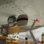
Thanks to some photos helpfully posted on a VAF thread, I decided to figure out the installation of the fuel flow sensor.  I fabricated a mounting plate from some scrap .125 bar stock, which attaches to a pair of engine mount tubes via Adel clamps.  The sensor mounts to the plate using it’s own 1/4″ mounting holes, for which I of course don’t have the correct length bolt (AN4-17A).  I also need to order the steel nipples for the in and out of the sensor; the sensor ports are 1/4″ NPT, rather than the 1/8″ commonly associated with the -4 fluid lines, so that will require the “-4-4″ nipple, which is 1/4″ NPT to -4 flare.  I cut off the spade terminals on the sensor wires and fit a 3-pin Molex instead, then ran the harness wires to the sensor location and connected the two.  I also installed Adel clamps to strain-relief the wires both at the sensor and at the connector.  Since the mounting plate floats in space between the two engine mount tubes, it’ll be possible to wrap the entire assembly in a piece of firesleeve.
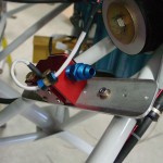
With the FF sensor located, I set about measuring for fuel lines, and re-checked all the ones I’d measured previously.  I have a list of 8 hoses that need to be made up now.  There are two more yet to be measured, for the oil cooler lines, which won’t be evident until the oil cooler arrives and is at least mocked up in place.  Plus, the brake lines, but at least those are already known lengths.  The steel oil cooler fittings will also need to be ordered.

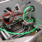
Moving back inside, I experimented with various locations for the pitot/static manifolds.  Fabricated a bracket to mount both, one atop the other, and mounted it to the subpanel.  I need to pick up some longer #6 screws to mount the manifolds to the bracket, though.  Trimmed and inserted the pitot and static lines, and a pair of jumpers for EFIS 1.
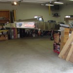
Also spent time cleaning the shop, tossing/recycling the large pile of debris that had collected under the plane.  Storm season is here, and I need to get at least one vehicle inside when weather threatens (as it is this weekend).  I figured out that I can move the fuselage 90 degrees to the right and Allison’s car will tuck nicely under the tail.
Passed 1300 hours in this session.
Hours: 8.2 | Posted in Electrical, Engine, Plumbing | Comments Off

2nd April 2011

Forward cabin loose ends

More wrapup of loose ends in the cabin area, mostly dealing with the last of the electrical:

  • Installed the DB-37 connector shell and hood for the ADS-B, and tied up that bundle.
  • Installed the hood on the ARINC module connector.
  • Soldered the 3.5mm jack on the ADS-B maintenance port connector, enlarged a tooling hole in the subpanel, and installed the jack there.
  • Fabricated engine ground cables and installed between the firewall ground buss and the engine case.
  • Measured for throttle and mixture control cables.
  • Cut and installed the ducting between the vent scoops and the panel vents.  (Need to get some screen mesh to put on the vent scoop end to prevent ingress of bugs.)
  • Removed the parking brake cable from its mount, so that the mount could be removed and painted.  Realized that the ball bearing fell out of the cable mechanism; spent some time searching for it in vain.  (Hint to similarly troubled souls: ACS sells replacement balls for $2 apiece; a bag of 50 is under $5 at McMaster, and then you can lose it 49 more times.)
  • Swapped out all the screws on DB connectors for thumbscrews…much easier to work with, especially upside down under the panel.
  • Installed a snap bushing in the left subpanel rib for the pitot and AOA lines to pass through.  Ran those lines up the left vertical FW stiffener and tied in place.
  • Tidied and tied up the bundles of wire in the tunnel.
  • Cut pieces of vinyl tubing to slip over the tubing in the tunnel for anti-chafing at tiedown points.  With much contortion, tied up the fuel and brake lines in the tunnel.  Still a couple to do, and one tiewrap base where the glue is obstructing the hole; it may be possible to open it up with some safety wire.

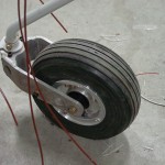
The day’s other task was attempting a redo of the nosewheel bearing.  When I installed the wheel before hanging the engine, I noted that the rotation was quite stiff.  I have the Matco axle which was supposedly designed in part to alleviate that problem.  It’s very stiff…one theory was that I didn’t manage to properly grease the bearings (they are tricky to hand-pack with the molded rubber seal).  So I bought a bearing packer cup, which did a fine job of packing it; grease squeezes out under the seal.  Re-installed, and no change.  If I tighten down the ring on the axle that’s supposed to set the preload (the instructions say to tighten it until the bearing face does not rotate with the wheel), the wheel requires what seems to me to be a lot of force to rotate.  Given the discussion around the nosewheel issues, this doesn’t seem right.  The bearing cones feel fine on inspection, too.  Anyone out there with experience installing the Matco axle that can confirm or point out where I went wrong?  For now, put it back together, knowing at least that it is well-lubricated.

Hours: 5.7 | Posted in Electrical, Gear & Fairings | Comments Off

29th March 2011

Serial ports

Made up the service cable tonight; a DB-9 to connect to a PC on one end, and a 3.5mm plug on the other.  I’m installing several 3.5mm jacks throughout the plane as places to tap into serial lines for programming and service:

  • Left Pmag (connects to control port)
  • Right Pmag (control port)
  • NavWorx ADS-B (maintenance port)
  • APRS transmitter (normalling jack; interrupts GPS signal for programming)

I headed to the shop to test the cable, and soon discovered that I had wired the jack for the left Pmag backwards; TxD was RxD and vice versa.  Swapped that with the soldering iron, and I was able to connect with both Pmags.

Also verified that the GPS was sending its data out, as I wasn’t able to get it to display on the transponder the other night.  It’s definitely outputting, so some more research on the GTX 327 had inconclusive results as to whether or not the box would take NMEA.  It’s supposed to work for sure with Aviation format, as output by the GNS430 (and presumably the new GTN series), to which it’s wired.  I had planned to run NMEA into those pins from a mating connector, which would feed the transponder and autopilot, but now I’m not sure if it’s necessary, assuming the transponder has no use for it.  I suppose the autopilot can still read it, if I buy that before the GNS/GTN.

Hours: 1.0 | Posted in Electrical | Comments Off

28th March 2011

Wire here, wire there

Some new info on the wiring for the interface between the NavWorx, AFS, and GTX 327 transponder came out, which meant moving one wire and adding another wire, so that’s what I did tonight.

Hours: 2.3 | Posted in Electrical | Comments Off

27th March 2011

Electrical loose ends and misc.

Worked on a laundry list of essentially small tasks, which filled up most of what turned out to be a fairly productive day.  I’m approaching the point where I need to order a bunch of stuff in order to continue installing things (like control cables, exhaust, FWF plumbing, and so on), but that’s likely to be delayed for a few months for finances, and it’s likely that if it’s delayed into May, it’ll be delayed until fall.  Oh well…perhaps the summer project will have to be tips, fairings, and wheelpants.

  • Finished programming the VP CU and testing electrical continuity and switching to all the devices which are installed.  Even plugged one wing in to check out the taxi light, and the wig-wag.  The VP config program, along with the Ethernet connection, is pretty slick.
  • Fabricated the attach point and pushrod for the flap position sensor; installed the sensor and adjusted the pushrod for appropriate travel.  Monkeyed around with the VP flap options, checking out the momentary feature which uses the pos’n sensor to run the flaps to pre-determined stops.
  • Fabricated and installed doublers for the comm antennas, which tie into the seat ribs for extra stability.  Terminated the L antenna coax and installed both antennas.
  • Terminated coax and installed the ADS-B antenna.
  • Installed the aileron pushrod boots.

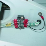
  • Made up and installed a wire to tie the shields of the nav/strobe light cables to ground; per AeroLED’s recommendation, these are tied to airframe ground at the terminal block under the LH seat pan.
  • Installed a tiewrap base to secure the pilot stick grip connector, and secured it.

  • Bolted the throttle quadrant to the panel; both the quadrant and the panel now have added stability.  This is at least temporarily bolted in place, so I can get an accurate measurement for ordering control cables.
  • Swapped out Adel clamps on the center heater control cable, now that I have the correct size on hand.
  • Installed an Adel clamp on the parking brake bracket and adjusted the cable end to swing to the correct angles for open/closed.
  • Used a pair of Adel clamps to stand-off the parking brake cable from the LH fuel vent line.
  • Went on an Adel-clamping marathon FWF, establishing wire runs along the engine mount tubes and getting the sensor wires going in the appropriate directions.

  • Installed and safetied the oil temp sensor bushing w/crush gasket, and the oil temp sensor.  Wired the sensor.
  • Installed the fuel and oil pressure sensors on the sensor manifold, and wired both sensors.
  • Wired the manifold pressure sensor.

  • Wired both Pmags and secured the wires with heatshrink and Adel clamps.  Tested power to the Pmags; the LED’s lit up, so I’ll assume it’s good for now.  The install docs warn against doing much of anything without the ignition leads connected, so I didn’t put them in “run” position.  Tried to install EICad (the Pmag programming software) on my laptop, but the setup program fails; it may not like Windows 7.
  • Installed new lockwashers where a couple Pmag mounting nuts had been loosened for access or installation, and torqued.

  • Temporarily hooked up the power harness for the Reiff engine heater, and plugged it in for a test.  It gets warm pretty fast!  I know there isn’t much oil in the sump now to heat, but it had the engine case warm, and the cylinders warming, without much delay.
  • With the antennas, terminal strips, pushrod boots, etc. in, I shouldn’t need to get under the seat pans for awhile, but it will be nice to sit in the plane to program avionics and check things like rudder pedal location…temporarily installed the seat pans with a reduced number of screws.  I’m planning to use stainless button head hex screws and washers on these, so this was a good test of that plan–worked perfectly.  I should pick up a set of ball-end hex drivers for doing these in the future.  (Note to self: seat pans are reversed, the right one should be on top at the overlap…will reverse when next removed.)
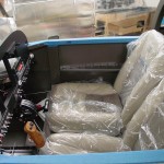
  • With the seat pans in, put the seats in (still wrapped in plastic; I’ll also need to pick up some towels or something to protect the seats on ingress/egress).  Climbed in and had a sit for a minute…looks like the rudder pedals will need to be at the most fwd position, which surprises me since I’m not terribly long of leg.  Might also try the seatback in the aft hinge, but I was pretty comfortable at the angle they were at in the middle hinge.

  • Tossed the charger on to top off the battery, as I’ve been running power for periods over the past few sessions of electrical install.

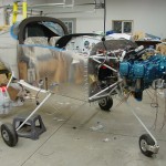
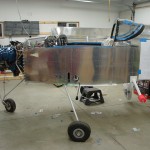
And a couple of “big picture” status shots for those who wonder what the plane actually looks like these days…

Hours: 9.3 | Posted in Electrical, Engine | Comments Off

26th March 2011

Electrical brain

Today I installed the real VP CU in place of the blank shell that was used for mounting and wiring, after testing the power to everything that’s installed.  (There is a lot of gear that gets power but doesn’t yet exist–ELT, APRS, EFIS’s, 430, and so on…as well as things in the wings that aren’t connected at the moment.)  Of course, I discovered that I had stupidly reversed the gender of the DB connectors; I had read the sheet as indicating the cable gender, where it was really indicating the gender on the CU.  So, all those pins were cut off and recrimped.

With the connectors sorted, I was able to power up the box and hooked the computer to it to begin programming and testing.  Had time to program just a few pins before it was time to go to work.

Hours: 2.1 | Posted in Electrical | Comments Off

24th March 2011

Let there be sound

Finished pulling the phone and mic lines through the airframe, and soldered them to the corresponding jacks.  Terminated the transponder and #2 comm antenna coax and installed the antennas, at least temporarily (they’ll eventually have a bead of sealer underneath).  I may end up putting doublers in for the comm antennas, as the skin flexes a fair bit with left/right motion of the antenna.

The audio system essentially complete, I had an urge to test if the jacks were wired correctly.  Slid the audio panel and intercom into their trays, hooked up the two test leads from the VP kit to the master buss feed (one at a time, first) and flipped the switch…lit right up, beautiful.  Once I had both running together (I knew there must be a reason VP provides two test leads!), I fetched my headset and plugged in.  Works like a charm; audio is there, the PTT’s on the stick and the canopy deck work.  I had to look up how to adjust the sidetone volume on the SL-40, as it comes set quite loud.  Tested the copilot side too, also works.  I think I have an old headset knocking around in some random box, I’ll have to pull it out and test it so we can both plug in at once…better than standing around talking to myself on the intercom!  I couldn’t remember the AWOS freq for any of the local airports, though I doubt it would have come in anyway (nearest field is ~15 miles away).  No music input handy to check that with, so that’ll come later this weekend.  No noise heard from the panel or cabin lights, either.

Hours: 3.9 | Posted in Electrical | Comments Off

22nd March 2011

Light at the end of the wiring

Finished up the wiring of the GPS/Icarus distribution block, crimped sockets on the ADS-B wires, and checked through the wirelist for the 430.  Everything had been run except the ground wires, which were somehow left out, so I ran those in place.  That essentially finishes up all the behind-the-panel avionics wiring, so I went through neatening and putting final wire ties on everything.  I still need to terminate the cables to the 430, and run the mic/phone lines aft.  Started feeding those through the fuselage, and got as far as the spar before bed called.

Once those last few wires are in, all that’s left to do electrically is plug in all the boxes and fire it up.  Wiring has taken more time that I expected, and it doesn’t look as perfect as I’d hoped, but I enjoy the process and the work, and it’s a bit sad to see the end; though I’m excited to get the AFS screen and light that up.  I expect that something will have gone awry and will need troubleshooting, too.  Next, it’ll be on to the engine sensors and control cables, which means I should get the exhaust on order (and sort out what prop I’m going to use, so that can be ordered if it has a long lead time!)…but with the avionics purchased, I’m back to waiting for the money tree to bloom before any of that can happen.

Many tie wraps were harmed in the making of this project…

Hours: 3.3 | Posted in Electrical | Comments Off