Beginning panel electrical
Hours: 6.9 | Posted in Cabin & Interior, ElectricalI often find myself bouncing around the project lately, where I may be working on three little jobs at once in different parts of the shop…waiting for paint to dry on a couple things, for instance, while drilling something and wiring something else. So when I sit down at the end of the day to write these logs, it’s sometimes challenging to think back and remember everything I did that day. Pictures help, but I’ve had a bad time remembering to take a photo of every little job, too.
Today’s work…
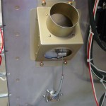
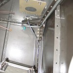
- Riveted the right cabin heat control bracket to the vent bracket, which was then riveted to the side skin. Installed the control cable and secured it, which required some modification to the firewall passthru, as the cable was just slightly loose in the eyeball. I used a flat file to shave just a bit off the flat side of each ball halve, which allowed it to get a firm grip on the cable and secure it in place. Cut the casing and cable to length and assembled. Installed the right side vent nozzle.
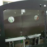
- Traced the spare round-gauge hole, and the autopilot head hole, onto scrap stock and cut it out to make filler panels for those cutouts, since they will not have instruments installed in the until phase two of the panel.
- Fabricated angles for mounting the radio stack to the panel. Waiting to drill them to the panel until the radios are in hand, in case the width of the trays is a bit off of the width of the panel cutout.
- Cut a hole in the subpanel behind each EFIS screen to pass the wiring harnesses and pressure tubing. Also put a hole in the lower right subpanel for the wiring feeds to the switches on that side of the panel, in addition to the hole that’s already made for running cable to the dimmer module. I have a couple sizes of nice rubber grommets from McMaster, in addition to an assortment of snap bushings that I bought from Van’s awhile back; finding the right size for a particular hole is easy.
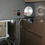
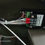
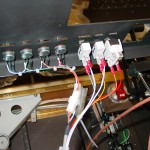
- Wired up the dimmer pots and interior light switches, then dropped the panel in to test them out. While the panel was in, I ran wire for the accessory power jack and the music input jack next to it (though this wire may end up being a placeholder, if this wire is already in the harness from Stein).
- Ran a wire to each Pmag for the serial port connection. I will bring each of these to a jack on the subpanel for ease of connection with the computer utility. The rear-mounted APRS transmitter will have a similar jack on the baggage bulkhead for programming.
- Test-fit the CO/SpO2 sensor. Can’t use washers on these screws, because the mounting holes on the piece are too close to the protruding bezel. Decided I need to get some #10 capscrews for the throttle quadrant mount to the panel, which should work better than bolts due to clearances (sockets were getting wedged in place).
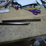
- Cut the plastic U-channels for the switch backlights, and painted them black. Cut LED strips to length for each piece of channel (3 total), and soldered leads to them. After testing them, it looks like another layer of paint will be necessary; the light bleeds through the sides of the channel.
