15th
January
2011
Random electrical
After spending much of the day getting the CAD panel design wrapped up, I worked on a bunch of little things, mostly electrical, tonight. I was stymied in a couple places by many of my tools and supplies being at the office, so some jumping around was unavoidable.
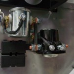
- Assembled and installed protection diode on the starter contactor, then torqued nd marked the contactor mounting bolts…this means the contactor install is complete.
- Placed the battery in the battery box.
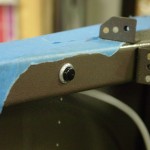
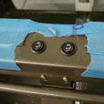
- Drilled holes for the auxiliary PTT switches (both left and right; right is essential for when the copilot stick is out, and the left will be handy to transmit without disturbing the stick when on autopilot).
- Installed a Molex connector on the map light panel leads to allow for easy future removal for service.
- Installed a Molex connector on the flap motor leads; same idea, especially knowing that this in even more likely to need to be serviced in the future than the LED map lights.
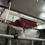
- Played around with some ideas for mounting the Vertical Power control unit; I could use the upper firewall angle as one mount point for a pretty clean install, but the mounting screws would be nearly impossible to get to after the top skin was on. I think I will run a pair of angles left-right across the bottom of the forward ribs, and mount the box to those. That’ll also provide for a good way to run wires left-right across the cockpit, and to strain-relief the harnesses to the control unit. The main buss wire looks like it will have a manageable path, as well.
- Drilled and installed the heated seat switches in the crosspiece aft of the seats. This position will require loosening a harness to reach in flight, but it solves the problem of needing to pass a bunch of wires through the spar. I saw this in a local builder’s plane recently, and he mentioned that downside, but said he would probably do it the same way again. I’ll only need two wires through the spar this way (both seats are sharing a power pin on the VP-X).
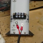
- Located and installed a terminal block on the vertical member under the crosspiece for the heated seat power. Removed the plastic connector from the end of the harnesses and installed ring terminals for connection to the terminal block.
- Looked at where to mount the heated seat relays; I plan to put them in the tunnel under the baggage compartment, mounted to the outboard sides. I temporarily installed the elevator pushrod to ensure there won’t be any interference.
- Modified the connectors on the seat heat harnesses by removing the mounting tabs, which aren’t used in this configuration; this makes them a bit smaller, to better fit in the tight spaces they need to run in. Disc sander make quick work of this.
Hours: 3.6 | Posted in Electrical | Comments Off
