Panel planning
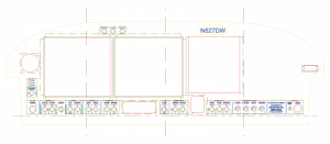
Having my phase 1 panel components on order from SteinAir, I thought it was time to get serious about designing the panel layout. Hence, I invested about ten hours over the course of an evening and the next day drawing my panel in TurboCAD. I have the software from work, and have used it for several things in the past, but it’s been several months so it took a bit to get back into the swing of things, especially as I know just enough of how to work it to get by. (Tip if you’re looking for a place to start: learn all the things you can use Constructions for…)
My thanks and apologies must go to Mike Behnke here — I really like the way his panel turned out (and Bret Smith’s as well, which they collaborated on). He graciously sent me his CAD file, which was a great starting point for layout and measurements. I used the DXF of the panel blank available from Vans’ website, since I have a tip-up, and copied some of Mike’s pieces, then drew all the stuff I wanted, often based off of stuff in his file or that I had seen elsewhere.
One of the pieces that I’m including is backlit switch labels, which include a series of cutouts behind certain legends on the panel which will be illuminated with an LED light strip. The engraved labels will lay over the cutouts, so the design is integrated using multiple CAD layers, so everything can be correctly aligned, then extracted and sent to the respective vendors for machining.
I really enjoy the process of designing these systems, and drawing up the layouts as well. While the overall layout is inspired by others, I’ve done a bunch of designing, either on paper or in my head, on alot of the electrical systems that will be in the plane. It’s satisfying to sit down with the electronics catalog and datasheets and think through different ways things could work, and come up with switchology or buttons or indicators that work the way I do, and finding the right parts to make them work and look a certain way. I enjoyed the metalworking part of the project too, but I’m especially partial to the systems stuff.
Once I had the panel design pretty close, I printed it out on tiled sheets of paper and put them together, then sat for a bit and looked it over in actual size. Put the dimmer knobs over the drawing to make sure they were spaced far enough apart that they could be grasped, and so on. Made some adjustments and tweaks, and set it aside…I’m sure another round of looking later in the weekend will reveal a few more things that come to mind. (I also need to do some measuring to ensure there won’t be any interference between the EFIS and the canopy stiffeners.)
I’ve planned for dual AF-4500′s, along with the Garmin stack: 240, 430W, SL40, 327. The flat-pack autopilot head mount is integrated into the row of controls at the bottom of the panel, along with the CO detector/pulse oximeter. Flap switch is above the throttle lever for ease of operation. There is enough space on the right side of the panel for an AF-3400 or other EFIS screen, if future expansion is desired, and I’ve put (at least for now) a 2.25″ instrument hole on the left as well, which could be used for some sort of backup instrument (such as the Trutrak ADI) down the road. The bottom flange has been dropped 1.25″ from the stock panel to give additional height for all the gizmos.
Once this is finalized, it’ll go off to someone to be cut by waterjet or CNC, and the labels to be engraved. When the avionics arrive, hopefully I’ll be ready!
Hours: 10 | Posted in Electrical | Comments Off

