12th February 2011

The small stuff

Not alot of visible progress for the hours today, just working on a number of small things.

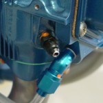
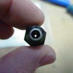
  • Assembled a .040″ restrictor orifice into a -4 straight nipple fitting, and installed into the #3 cylinder for pickup of manifold pressure.  The #10 sized orifice from McMaster-Carr (2943T887) works nicely in a -4 fitting size, just requiring the fitting to be tapped.  After tapping the fitting, I installed the orifice with high-temp threadlocker.  I also tapped the orifice from the hose side, rather than the cylinder side, so that if it were to somehow work loose, it could not travel into the engine, but into the hose.

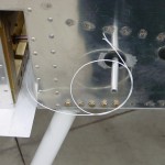
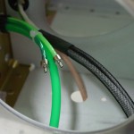
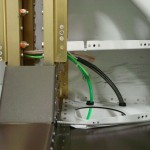
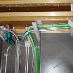
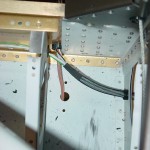
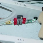
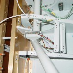
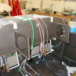
  • Finished installing the wing wiring connectors by terminating the wires on the left wing.
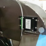
  • Reinstalled the fuel vent line tubing that passes through the fuselage sides; torqued the fittings.  Cut the vent lines to proper length.
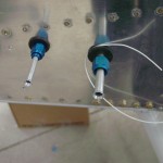
  • Smoothed and flared the ends of the fuel pickup and vent tubes that protrude from the fuselage.

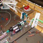
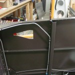
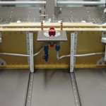
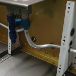
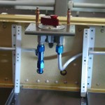
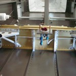
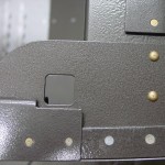
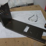
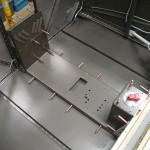
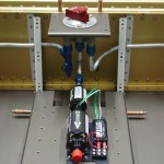
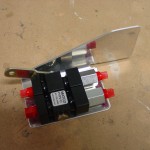
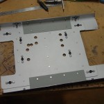
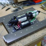
  • Riveted the doubler plate for the fuel pump to the tunnel cover.  Fabricated a pair of stiffener angles for the same cover, to beef up the sides of the assembly and reduce vibration.  Affixed the pump to the cover plate, and test fit it in the fuselage; tweaked a couple fuel line bends to get the selector-pump-firewall plumbing aligned.  Cut and terminated the fuel pump wires.

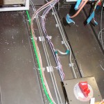
  • Put some temporary zipties on the tubing in the tunnel to hold things in place for now.
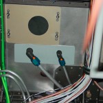
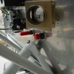
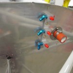
  • Removed the firewall passthru fittings to fabricate and install a doubler on the inside of the firewall.  I had used the thick aluminim spacer/washers that Van’s sends, but there was too much flex in the FW still for my taste; this beefed it up nicely.  Reinstalled fittings with doubler aft and spacers forward, and torqued fuel & purge return lines at the firewall.

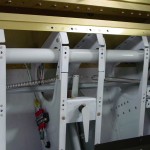
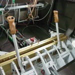
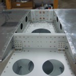
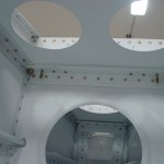
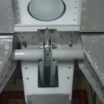
  • Installed the closure pieces for the inboard seat pan ribs, that bridge the gap which is cut to allow installation/removal of the control column.
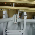
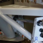
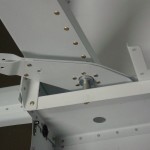
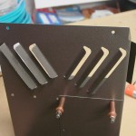
  • Temporarily installed the roll trim assembly in order to find the correct angle for the metal tabs that bolt to the lower end of the control sticks, so I could torque the bolts on the rod ends that tie the sticks together in roll.  Also to see how the trim goes together.  Followed the plans for setting the spring lengths, but they seem as though they might be overly tensioned…need to see where others have ended up on the length.  The issue may be that the plans have you use the forward-left-most stick position to set the spring lengths, and without the elevators and ailerons attached to hit their stops, I suspect the stick travel is a fair bit more than it would be normally, which would result in stretching the springs excessively.  So, setting the spring length may end up part of the after-final-wing-mating task list.
  • Also torqued the bolt for the elevator pushrod at the control column.

I found that the Goop used on the stick grips cured well, and the grips are solid.  Also sent off what I hope will be the last of the minor revisions on the panel layout, so that should be cut sometime next week and on its way.  Hoping to have the harnesses from SteinAir sometime soon, as that’s all I’m waiting on to wrap up the airframe wiring.  Had made contact with the engravers about doing the placards for the panel, but they seem to be slow on the email (or at least haven’t replied yet), so I’m not sure the current status of that piece.

Hours: 6.8 | Posted in Center Fuselage, Electrical, Plumbing | Comments Off
5th February 2011

Plumbing and wiring

Working on several areas today:

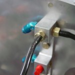
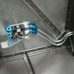
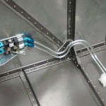
  • Installed 1/8″ NPT to barb fitting nipples in the transducer manifold for the manifold pressure line; one will feed MP to the P-Mags, the other to the sensor for the engine monitor screen.
  • Fit and temporary-installed silicone tubing from the manifold to the P-mags, and a stub for the MP sensor when it arrives.
  • Measured for fuel hoses and pressure sensor lines (fuel, oil, MP) with a piece of tubing.  I should now have the list of most of what I need to order, except for the oil cooler hoses, which I won’t be able to measure until baffles and cooler are installed.
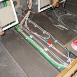
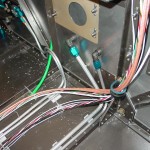
  • Ran wire from the panel to the wing roots, forward of the main spar, for the fuel level sensors; wires I forgot in the earlier wiring work to those locations.
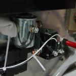
  • Pulled wires to the FWF electrical area, for master contactor, starter engage, and starter engaged annunciator.  Terminated and landed the contactor ends, and verified proper operation of the contactors.  Secured the wires, at least for now.  These should eventually get high-temp tie-wraps.
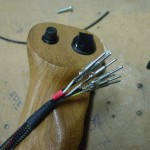
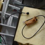
  • Wired the connectors on the stick grips, and glued the grips on with Goop.  I’ll have to see how it cures in a few days, whether it’s too soft for this or not.  I believe it will be removable with enough force, which would be a positive thing if I ever wanted to change grip function (add a switch, for example) or if a wire needed to be repaired.  But, I want it to feel solid, and the grip not to move or flex under normal use.
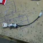
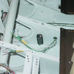
  • Put connectors on the master keyswitch and the aux PTT switches.  These connectors aren’t strictly necessary, as the wires could be soldered to them inside the plane, but soldering is a much more pleasant experience when not carried out upside down; I also want to be able to remove the panel without the need to unsolder things, which means a connector on the master switch, since it installs from the front of the panel (unlike the toggles, which install from the back with nuts on the front side.)  Installed the aux PTT switches, and glued a tie-wrap base to the underside of the forward canopy decks to secure the PTT wires and static line.

Hours: 7.3 | Posted in Cabin & Interior, Electrical, Plumbing | Comments Off
29th January 2011

Still more airframe wiring

First item on today’s list was the intake studs on the engine sump.  The ones that were on the engine as shipped were too short for the fuel servo and spacer/mount bracket, so Aero Sport Power sent out a set of longer ones.  The shorter ones were removed last week, and I picked up some high-temperature threadlocker (Permatex 27200) to put on the new ones, as recommended in the Airflow Performance install manual.  A few drops on the far end of the stud, a pair of nuts, and they were on and looking good.  Test-mounted the bracket and servo to make sure the length was good (it was), and to look at routings for control cables and fuel lines.  I’ll hold off on all that until I have an exhaust system, so as to not create any interference.  Also need to work out the location of the fuel flow transducer, which will go in the feed line between the servo and the spider which sits atop the engine.

Trying to get the airframe wiring (wiring that runs to various parts of the plane — as opposed to the panel wiring, which would connect the boxes on the panel and generally contained within the “avionics bay”, or engine wiring, which would run to the forward side of the firewall) generally wrapped up.  I have just about run out of space in the bushings that run through the center section, and still more wires to run, so it was time to add another bushing.  Evaluating various cable paths, I decided to put it under the fuel valve, to the right side, 2/3 of the way up the spar web, which would allow the wiring to run without chafing on fuel lines or interfering with the control column, and kept a good distance away from the other bushing holes.  A pilot hole a long #30, then a unibit made quick work of the holes, and I was able to use a 1/4″ drive handle to turn the unibit inside the center section to deburr the backside well.  Primer, then snap bushings.  (Tip: the snap bushings have a “ridge” on the inside diameter of the flange side that can be removed with a unibit, giving you an extra 1/16″ diameter…I’ve done this to all the bushings in the center section, to gain as much space as I could.)

More wires to run…2 coax lines for GPS antennas behind the rear window, plus power and ground for the ELT and APRS.  Need to look and see what the specified wire is for the magnetometer runs, as well as the GPS feed to the ELT/APRS (which will share a single feed line).  Also finished up the last of the wing wiring with the OAT, pitot heat, and landing/taxi light wires.  I tied up the bundles that run from the tunnel out to the wing roots, and sleeved the wires that pass out of the fuselage.  These will get CPC connectors on both sides, and the sleeving will be maintained all the way into the connector backshell.  I also put the straight union connectors on the AOA lines — the tails from the wing will pass into the fuselage, where they’ll be joined under the seat pan.  May do the same with the pitot line, but for now it’s run out the side.

Terminated the nav/strobe wires at the terminal block under the seat; this looks like it ought to work out alright, though were I to do it over, I would have put the snap bushing for the aft wires farther away from the terminal block.

Hours: 7.5 | Posted in Electrical, Engine, Plumbing | Comments Off

24th January 2011

More electrical and plumbing

Not much to look at, so not many photos today.  Ran more wires and tubes, including the wires for the stick functions, and mounted a terminal block for the nav/strobe lights.  The power will feed to this block, then run to the wingtips and tail…this makes it so that only 1 cable needs to pass through the spar, rather than 3.

Hours: 4.2 | Posted in Electrical, Plumbing | Comments Off
23rd January 2011

Electrical and plumbing

Installed the bulkhead fittings on the firewall for the fuel feed and purge return lines — I think I will also install a doubler on the aft side of the firewall that picks up both fittings, as they’re a bit wobbly yet.  Bent and test-fit the fuel line from pump to firewall, and fabricated a purge return line to run from the firewall back to the tee under the fuel selector.  Installed the elbow fittings in the transducer manifold.  Mounted the 4-channel lighting dimmer, and ran more wires.

Hours: 6.1 | Posted in Electrical, Plumbing | Comments Off
28th June 2010

Building the tail

First things first, a plumbing tweak.  I was stumbling around on VAF last night on a completely unrelated topic when I came across a thread about fuel vent routing.  Those lines that I was so happy with had to be adjusted, because I ran them to the top of the bulkhead at a 90-degree angle, which would later interfere with the mouting of the subpanel.  This post has a picture which illustrates the issue.  Not a big deal, I just removed the adel clamps on the aft vertical run, undid the bottom fitting, bent the correct angles at the top, then trimmed the lower portion of the line and re-flared.  The plumbing is really done now…I think.

Fuel vent line with correct 45* bend

Nextly, back to work on the aft end of the plane.  I finished drilling up the holes in the horizontal stab, then attached the elevators and fitted the counterweights.  The right elevator is a bit nose-heavy, while the left is almost dead-on balanced.  Supposedly, nose-heavy is the way you want to be before paint, since there is more surface area (thus more added paint weight) aft of the pivot point.  Clamped the counterbalances to the stabilizer in preparation for fitting the pushrod.

Horizontal stab drilled to fuselage Underside of forward HS attach bolts Elevator horns and center bearing

Elevator counterweights bolted in HS and elevators in place

Since the pushrod needs to be fabricated and primed, I took a diversion next to install the control column.  This meant attaching the pivot brackets to the spar, then building the control column on top of them.  This task is complicated by all the various washers to be installed, and I had to fiddle with a few different combinations in order to get it to move smoothly.  After a final test fit and adjustment (these were initially fit during assembly of the center section bulkhead), I greased up the brass bushings and bolted the sticks in place.  I should be able to install the grips and wiring without removing them (crimp the pins, slide the wires down, then insert the pins in the connector), but I’m leaving the cotter pins out for now just in case….it’s s tight space and I’d rather only fiddle with cotter pins in there once.

Control column installed Detail of control column mounting

Hours: 4.9 | Posted in Plumbing, Wing & Tail Joins | Comments Off

26th June 2010

Fuselage plumbing victory

First order of business tonight was to attend to the misplaced fuel lines.  It turned out okay to pull them out from the inside, then re-run them in the correct holes.  Due to the differing geometry of the bends, the left line was re-usable, but the right line, when re-run and bent to mate with the selector, was too short — only about 2″ protruding from the fuselage, instead of the 4″ I was aiming for.  (Notes from other builders indicate that the necessary length is around 2 5/8″.)  So, out came the right one and I re-made a fresh line, using the coil of tubing I had set aside with the fuel pump output bend in it.  I cut it to the approximate length I needed, using the removed line as a guide, and it looks like there will be enough tube left to complete the run to the firewall, which is good news.  Crisis averted.

Fuel lines re-run in correct holes Detail of fuel lines below selector

Next on the list was the brakes.  I finished fabricating the parking brake valve bracket, drilled the holes for the valve mounting bolts, drilled for nuplates, match-drilled the firewall (nutplates will go on the forward side of the firewall so that insertion and removal of the valve won’t be a two-man job, especially should it need to be removed for service).  I set this up to have the control cable go off to the left, as I liked what I saw in some panel photos today that had the parking brake control tucked under the panel and forward, along the left side of the cockpit.  It makes sense to keep it off the panel, being a not-often-used control.

Test fit of the brake valve looked good, so I installed the appropriate fittings and went to work on the brake lines.  Bending the lines around the angles at the firewall took some conjuring, but it wasn’t all that bad. Once the bottom tube (which will be the left brake) was made, the top one was essentially the same, with adjustment in the bend radii as needed so the tubes would essentially parallel each other.  I bent the front half of the tube, then estimated the length for the run along the spar, cut, bent the transition, and ran the tube out to the gear tower.  Repeat for the right side.  Installed the bulkhead fittings in the gear towers, as well, so that end of the lines could be torqued in place.  The valve end of the lines will wait until later, since the valve bracket still needs to be primed and riveted.

Brake lines and valve test fitting Brake lines at firewall Brake line outboard end Fuselage plumbing essentially complete

Hours: 4.9 | Posted in Plumbing | Comments Off
26th June 2010

A step back on fuel lines

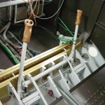
Well, maybe the ease of installing those fuel lines yesterday was a sign that something was amiss.  I realized after looking at some pictures on other web sites that I ran the lines through the largest (top) bushing, thinking biggest tube = biggest bushing.  Not so…the largest bushing is for the wiring bundle.

Not a problem, right?  Just get some 3/8″ vinyl tubing, slit it lengthwise, and slide it over the tube into the bushing to take up the space and provide cushion, then pull the bottom bushing, drill out the hole, and install another large bushing.  Not so fast, according to a thread on VAF:

It is only Kosher if you don’t run any wires under it. Should you have a leak, the fuel could drip on the wires and that may not be a good thing.

Any Tech Advisor worth his salt would ask you to move the fuel lines to the bottom holes.

[...]

….don’t run the fuel lines above the wiring….it’s not acceptable aviation practice (ie very dangerous).

[...]

When in doubt you can always refer to the bible (AC43.13). Section 8 says: “Where practical, route wires and cables above fluid lines”.

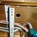
Vans RV7 DWG 11 also specifically notes that the bottom snap bushing in the relevant cover support ribs (F-783B and F-783B) is an SB500-6 for the 3/8″ fuel line. The top snap bushings are an SB625-7 for the electrical wires.

Sigh.  Looks like I’ll be ordering another spool of 3/8″ tubing.  I almost put one on the last order…wish I had, it would have been a guarantee that the first time would go perfectly and I’d never need to touch the extra.  I don’t know that I’ll be able to pull these out intact and have them be the correct length, etc.

Posted in Plumbing | Comments Off
25th June 2010

Fuel lines & other fuselage miscellany

Finally conquered the selector-to-filter line, after the umpteenth iteration.  I ended up not using the swivel elbow on the filter inlet, because the short tube was impossible to bend and have room to slide the sleeves on and flare.  (The Rolo-flare, plus the sleeve, requires about 1 1/4″ of straight tube at the end to accomplish the task.)  Once that was done and in place, I mocked up the required bend to get the pump outlet routed down under the tunnel cover, with a piece of scrap, then replicated that in the end of a long piece of tubing…that’ll sit on the shelf for awhile until I determine where the firewall penetration fitting will be, at which time it will be run up there.

Selector-filter tubing Pump output tube

With the selector and pump solidly in hand, I moved on to the tank-to-selector plumbing.  These are the lines everyone talks about, that they’re so difficult, and the latest fad has been to use flex hose instead.  I actually found them rather easy, but maybe that was just relative after the three-day battle with the aforementioned connection.  I ran the spring bender through the side skin and the gear tower, then fed the tube in little by little, guiding it through the snap bushings until the end was at the fuel selector.  Bend as required, flare, done.  Repeat for the other side.  The right is slightly different than the left, as I have provisioned a tee for the AFP injection purge return line into the right tank feed line, just below the selector.

Fuel plumbing in place Tank feed lines installed Right tank feed line through weldment

Took a moment while I had the fuselage on its side to install and torque the elevator bellcrank.  Also trimmed the aft end of the canopy decks, which I had somehow missed in the earlier trimming…this removes the bit of the piece that would otherwise cover up the outboard portion of the canopy latch hole in the gusset plate below.  Easy with the Dremel tool and a cutoff wheel, followed up by some small files & scotchbrite.

Elevator bellcrank Trimmed end of canopy deck

Next was fitting the center tunnel cover…this wasn’t as bad of a task as I had been fearing.  The firewall recess was clecoed in place, then the tunnel cover set in place and measured for the proper spacing from the bottom skin.  #30 holes were drilled at four locations on each side, then enlarged to final size, and the holes were drilled into the firewall recess.  Cover was then removed and split in half, to allow the front portion to be installed separately from the aft portion.  This is necessary because the fuel line goes under midway up, forward of the boost pump, rather than under the selector.  All pieces deburred, nutplates drilled and installed, heater box louvers bent, then checked for fit again with all the rest of the pieces, boost pump, and tubing…very happy to see that the selector-filter tubing still fit correctly.  Removed covers and set aside for later.

Center tunnel cover Louvers in heater box Center tunnel cover temporarily in place Cabin fuel system test fit

What’s next…brakes!  I have the new Matco parking brake valve, which I plan to install in the same place that the bracket on the firewall is (using the valve as the transition point from flex lines to solid lines) — so the first step was to drill off the existing bracket.  Next, I need to fabricate a bracket that has a provision for fixing the control cable in place.  I drew out, cut, and bent one that holds the valve horizontally (so the lines enter left and exit right), with the control cable coming from the right of the valve.  Not sure that’s where I want the control, so I’ll be looking at what others have done to mount this thing.

Attempt at brake valve bracket

Hours: 7.9 | Posted in Plumbing | Comments Off
24th June 2010

Macaroni tubing

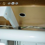
More time today trying to wrangle the dang selector-filter tube into place.  I put a swivel elbow on the filter — the vertical of the elbow and the outlet of the selector are misaligned by about 3/8″, which means that the tube needs to have a joggle in it…maddeningly difficult to bend, as the short, short bit of tubing (only about 4″) provides very little leverage for bending, and it’s just too short to fit in the lever-type bender.  I had one piece nearly right, just a touch too long…cut it down and it was too short.  Argh!  I almost had another one fitting well, when it was time to leave for the evening’s entertainment.  I’ve probably used up 6-7 feet of tubing for this 5″ distance.  Simply amazing.
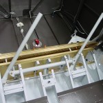
Note to future builders installing Andair selectors along with Andair pump/filter assemblies: don’t blindly use the measurements in the Andair drawings!  Set it up and think hard about this tubing run, and you might find it easier to use the tubing run to adjust the fore/aft position of the pump.  If I had set the pump 3/8″ farther forward (which would fit just fine), I could have used the swivel elbow and a nice, easy piece of straight tubing.  Live and learn…

Hours: 0.9 | Posted in Plumbing | Comments Off