Still more airframe wiring
Hours: 7.5 | Posted in Electrical, Engine, PlumbingFirst item on today’s list was the intake studs on the engine sump. The ones that were on the engine as shipped were too short for the fuel servo and spacer/mount bracket, so Aero Sport Power sent out a set of longer ones. The shorter ones were removed last week, and I picked up some high-temperature threadlocker (Permatex 27200) to put on the new ones, as recommended in the Airflow Performance install manual. A few drops on the far end of the stud, a pair of nuts, and they were on and looking good. Test-mounted the bracket and servo to make sure the length was good (it was), and to look at routings for control cables and fuel lines. I’ll hold off on all that until I have an exhaust system, so as to not create any interference. Also need to work out the location of the fuel flow transducer, which will go in the feed line between the servo and the spider which sits atop the engine.
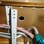
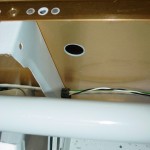
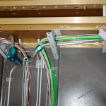
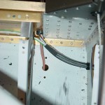
Trying to get the airframe wiring (wiring that runs to various parts of the plane — as opposed to the panel wiring, which would connect the boxes on the panel and generally contained within the “avionics bay”, or engine wiring, which would run to the forward side of the firewall) generally wrapped up. I have just about run out of space in the bushings that run through the center section, and still more wires to run, so it was time to add another bushing. Evaluating various cable paths, I decided to put it under the fuel valve, to the right side, 2/3 of the way up the spar web, which would allow the wiring to run without chafing on fuel lines or interfering with the control column, and kept a good distance away from the other bushing holes. A pilot hole a long #30, then a unibit made quick work of the holes, and I was able to use a 1/4″ drive handle to turn the unibit inside the center section to deburr the backside well. Primer, then snap bushings. (Tip: the snap bushings have a “ridge” on the inside diameter of the flange side that can be removed with a unibit, giving you an extra 1/16″ diameter…I’ve done this to all the bushings in the center section, to gain as much space as I could.)
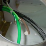
More wires to run…2 coax lines for GPS antennas behind the rear window, plus power and ground for the ELT and APRS. Need to look and see what the specified wire is for the magnetometer runs, as well as the GPS feed to the ELT/APRS (which will share a single feed line). Also finished up the last of the wing wiring with the OAT, pitot heat, and landing/taxi light wires. I tied up the bundles that run from the tunnel out to the wing roots, and sleeved the wires that pass out of the fuselage. These will get CPC connectors on both sides, and the sleeving will be maintained all the way into the connector backshell. I also put the straight union connectors on the AOA lines — the tails from the wing will pass into the fuselage, where they’ll be joined under the seat pan. May do the same with the pitot line, but for now it’s run out the side.
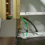
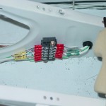
Terminated the nav/strobe wires at the terminal block under the seat; this looks like it ought to work out alright, though were I to do it over, I would have put the snap bushing for the aft wires farther away from the terminal block.
