14th January 2011

Panel planning

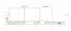
Having my phase 1 panel components on order from SteinAir, I thought it was time to get serious about designing the panel layout.  Hence, I invested about ten hours over the course of an evening and the next day drawing my panel in TurboCAD.  I have the software from work, and have used it for several things in the past, but it’s been several months so it took a bit to get back into the swing of things, especially as I know just enough of how to work it to get by.  (Tip if you’re looking for a place to start: learn all the things you can use Constructions for…)

My thanks and apologies must go to Mike Behnke here — I really like the way his panel turned out (and Bret Smith’s as well, which they collaborated on).  He graciously sent me his CAD file, which was a great starting point for layout and measurements.  I used the DXF of the panel blank available from Vans’ website, since I have a tip-up, and copied some of Mike’s pieces, then drew all the stuff I wanted, often based off of stuff in his file or that I had seen elsewhere.

One of the pieces that I’m including is backlit switch labels, which include a series of cutouts behind certain legends on the panel which will be illuminated with an LED light strip.  The engraved labels will lay over the cutouts, so the design is integrated using multiple CAD layers, so everything can be correctly aligned, then extracted and sent to the respective vendors for machining.

I really enjoy the process of designing these systems, and drawing up the layouts as well.  While the overall layout is inspired by others, I’ve done a bunch of designing, either on paper or in my head, on alot of the electrical systems that will be in the plane.  It’s satisfying to sit down with the electronics catalog and datasheets and think through different ways things could work, and come up with switchology or buttons or indicators that work the way I do, and finding the right parts to make them work and look a certain way.  I enjoyed the metalworking part of the project too, but I’m especially partial to the systems stuff.

Once I had the panel design pretty close, I printed it out on tiled sheets of paper and put them together, then sat for a bit and looked it over in actual size.  Put the dimmer knobs over the drawing to make sure they were spaced far enough apart that they could be grasped, and so on.  Made some adjustments and tweaks, and set it aside…I’m sure another round of looking later in the weekend will reveal a few more things that come to mind.  (I also need to do some measuring to ensure there won’t be any interference between the EFIS and the canopy stiffeners.)

I’ve planned for dual AF-4500′s, along with the Garmin stack: 240, 430W, SL40, 327.  The flat-pack autopilot head mount is integrated into the row of controls at the bottom of the panel, along with the CO detector/pulse oximeter.  Flap switch is above the throttle lever for ease of operation.  There is enough space on the right side of the panel for an AF-3400 or other EFIS screen, if future expansion is desired, and I’ve put (at least for now) a 2.25″ instrument hole on the left as well, which could be used for some sort of backup instrument (such as the Trutrak ADI) down the road.  The bottom flange has been dropped 1.25″ from the stock panel to give additional height for all the gizmos.

Once this is finalized, it’ll go off to someone to be cut by waterjet or CNC, and the labels to be engraved.  When the avionics arrive, hopefully I’ll be ready!

Hours: 10 | Posted in Electrical | Comments Off
6th January 2011

Round things, and things that go ’round

More items from the pre-engine-hanging punch list tonight…

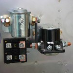
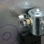
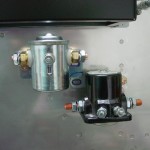
Installed the protection diode on the master contactor.  Need to order another diode for the starter contactor.

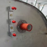
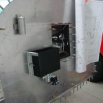
Installed the right-hand wiring passthru in the firewall, pretty much in a mirror-image location of the left one.  I found a number of builders who have put them here and said it worked well.  Their photos showed good wiring routes for everything, and it will be an ideal position for feeding the main buss wire into the Vertical Power box.  It also leaves open some real estate on the bottom of the firewall for the possibility of putting a heater box there.

Put the engine mount in place and snugged down the bolts to hold it.  Put the nose gear in and temporarily placed the bolt at the top.  I’m wondering if it would be a good idea to upgrade this to a close-tolerance bolt; I know some have tried taper pins but had a heck of a time reaming the tapered hole in the hard steel leg.

Decided to finish off the main gear legs, so hoisted the fuselage up one side at a time to adjust and drill the axle nuts for cotter pins.  The engine hoist and a double cargo strap to the gear tower worked nicely to get the wheel off the ground.  Since the gear-leg bolts are not yet torqued, it was easy to drill the top side, then pull the leg to drill the bottom hole.  After marking each hole with a drill bit, I removed the nut and ground a depression in the threads with a burr in the Dremel tool, then replaced the nut and drilled the hole.  Found this method on the forums, and it worked well to keep the axle threads from splitting and tearing up the nut threads.

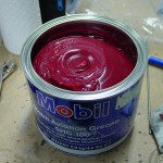
For the gear, I’m using the grease recommended by the maker of the main wheels, Mobil Aviation SHC 100, a non-clay-based synthetic grease.  The smallest quantity I could find to buy was the 4.4-lb can…that’s a lot of grease, and it’s spendy stuff too.  I’m using this because the main wheels came already packed with it, and the nose wheel isn’t packed with anything; may as well use the same stuff all around.

Still to do before engine hang: seal and install the firewall recess (which will involve removing the top skin), seal and install the wiring passthrus and brake reservoir, pack the front wheel bearings, and deal with the oil pressure fitting.  Need to look up the mix ratio for the CS1900 firewall sealant so I can mix smaller batches than the entire pint can.

Hours: 2.9 | Posted in Electrical, Gear & Fairings | Comments Off

4th January 2011

Firewall population

Installing more stuff on the firewall was the order of business again tonight…

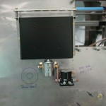
  • Painted the battery box and temporarily fit it in place (permanent install after firewall recess is riveted).
  • Riveted the nutplates for the oil/manifold pressure hose adel clamps, as well as the fuse block doubler & nutplates.
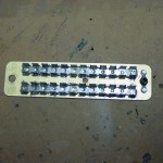
  • Installed the fuse blocks and buss bars.  Located one protection diode, but my crimpers are at work, and it looks like a second diode will need to be ordered.
  • Drilled and installed nutplates for the transducer manifold, and temporarily fit the manifold (needs to come back off to install the hose fittings, which I need to order).
  • Located, drilled, and temporarily installed the left-side wiring passthru (will install permanently with sealant).
  • Fiddled around again with locations for the right-side passthru and both heater boxes.  Still undecided.  Basic question for the passthru is high (like the left side), or low (nearer the contactors).  Saw a recommendation to locate them where the wiring has a graceful path to the engine mount tubes, so wiring can follow the tubes.  This can be made to work either high or low.  Looking for photos of other folks’ master buss cable installs.
  • Installed the fuel vent fittings in the bottom skin.  Still need to secure & torque the B-nuts.

Hours: 3.1 | Posted in Electrical, Engine | Comments Off

31st December 2010

Seats in, more electrical

More futzing with the firewall, getting bits and pieces in place while waiting for engine mounts to arrive.  The “forest of tabs” ground block from B&C arrived yesterday, so that was drilled to the firewall today.  I added an extra bolt at the end of the aft piece, to guard against any vibrations…installed a nutplate for it on the aft side, so the bolt on the fwd side could be used for an adel clamp or whatever if needed in the future.

Re-fit the fuse holders to the firewall and made up the copper bars that connect the two fuses, plus the bar that feeds the switched side of the battery contactor to the fuses, and the lug that will connect the battery cable to the contactor.  Once the copper bars were fit and drilled, I used some heatshrink tube to cover all but the ends, and notched the covers of the fuse holders to fit over the bars.

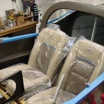
That done, I decided to fit the backrests and drill the seat hinges.  The install guide makes this seem a bigger deal than it actually was, and they went in pretty quick and easy.  I used the hinges I had made up during the fuselage build.  I may have to re-do the right side later with a new piece of hinge (Classic Aero includes hinge pieces, so I have spares), depending on how tight the canopy frame is to the seatback.

Also mixed up some proseal and glued the stainless screens to the fuel vent fittings.

Hours: 4.5 | Posted in Cabin & Interior, Electrical | Comments Off

27th December 2010

Firewall fiddling

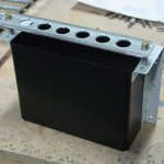
Drilled the lightening holes in the battery box with a hole saw, then cleaned them up with a rotary file and scotchbrite wheel, all in the drill press.  Will need to pick up a can of black spray paint for the box, as my can is shot (too many seasons of freezing, I think).

Dug out the “MIDI” fuse blocks and decided to mount them below and to the left of the contactors, so I fabricated a doubler plate for them; I need to order a bunch of different kinds of nutplates including single-leggers and corners–which I should have done awhile ago, but they’re spendy little things.

Drilled the holes for mounting the nutplates for the oil pressure line, but there too, need to order nutplates.

Hours: 2.3 | Posted in Electrical | Comments Off
26th December 2010

Battery box & contactors

Worked more on the firewall tonight:

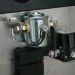
  • finished up and mounted the doubler for the contactors
  • installed the nutplates for the battery box and fabricated the battery hold-down bar and spacers
  • drilled pilot holes for the lightening holes in the box (need to bring my hole saws home tomorrow to finish the  box)
  • installed the nutplate for the breather hose
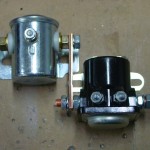
  • made up the copper bar that runs between the contactors and ground down the mounting ear on the master contactor so it will nest with the starter contactor
  • played around with possible locations for the wiring pass-thrus

Was going to install the two nutplates for the oil pressure hose as well, but can’t decide where they’re intended to be installed — I have seen pictures with them at the top corners of the recess, but turns out that hole location is a bear, since it has no flat spots for the “ears” of the nutplate.  So, more research.

Hours: 2.9 | Posted in Electrical | Comments Off
23rd December 2010

Holiday shop time

Took advantage of the “extra” day off from work (since Christmas day falls on the weekend this year) to get in some shop time, since the rest of the holiday weekend will be spent doing the relatives thing.  It’s been nearly a month since I’ve done any work on the project, due to work and more work…’tis the season.  I met my goal of wrapping up all my freelance projects by Christmas, so I should be able to use more of my time away from the office to work in the shop.  Having that engine sitting there is a motivator!

Before heading out, I put in a few orders to various vendors for parts, including Lord mounts and bolts, transducer manifold, baffles and airbox, firewall sealant, wheel bearing grease, etc.  Still plenty to order, but this should let me get the engine mounted.  Also talking to SteinAir to get panel build parts and engine sensors.

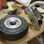
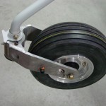
First order of business in the shop was assembly of the nosegear, since the leg will need to be in place to support the weight of the engine.  After assembling the fork with the various bolts and spacers, I mounted the tube & tire to the wheel and assembled it to the fork loosely (the bearings still need to be greased, once my can of grease arrives…).  I have the Matco axle and drilled that to the fork, but won’t adjust the preload setting until the bearings are greased.  I bolted the engine mount up temporarily to look at some spacing & layout things for deciding where to install various bits, and slid the nose leg into place.  At that point, I realized that I had installed the swivel stop piece backwards; the stops should be on the forward side of the fork, not aft.  An easy swap, dropping the fork and reversing it the right way round, and all is well.

As long as the engine mount was bolted up, I took the opportunity to address the spacers needed behind the inner bottom mount points.  It turned out that after filing the lower pump nutplate down to provide clearance, all that was needed was a .063 piece, so I fabbed two circular spacers from a piece of scrap and bolted them in to test…perfect.  Pulled the gear leg and engine mount, and set to work drilling holes in the firewall.

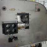
First, the brake reservoir.  Recommended locations for all this stuff if given on the plans, so it’s just a matter of measuring it out and drilling.  Well, then drilling more, countersinking, deburring the stainless firewall, and riveting nutplates… The reservoir went on fine; I ended up using three regular washers on each side to keep the top of the canister from rubbing the bent upper part of the firewall.  Next up, I measured and drilled the hole that’s needed for access to the nosegear leg bolt, which ended up being right where I had marked it with a drill bit through the bolt hole.  This will get a stainless plug to close it once the leg is installed.

Next on the list was the battery box, so I pulled that out and drilled/dimpled/riveted the side angles to the box.  I will drill the lightening holes later, since my hole saw set is still at the office from the big studio build. I drilled out the necessary rivets from the firewall and clecoed the box in place for now.  I’m intending to–as much as is practical–install everything on the firewall using nutplates on the aft side so that removal/installation can be a one-person job from the front, without having to crawl under the panel to twist wrenches.  The battery box is prepunched for nutplates to be attached to the mounting angles, then bolts run from the cabin side to attach it.  I don’t see why this couldn’t be reversed, and bolted on from the front, so I’ll research that to make sure I’m not all wet.

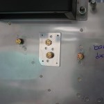
With the battery box clecoed on for spacing, the next logical step was the contactors, but I’ve read that the doubler in the plans may not put the holes in the correct locations.  Instead,  I drilled out the specified rivets and installed the nutplates on the stiffeners, and fabricated the doubler with no holes.  I bolted the contactors up temporarily and marked where the center holes needed to be for them to align well, then drilled those holes.  I’ll back-drill the doubler from these holes next session.

To do: figure out where all the other nutplates need to go on the firewall for breather tubes, oil pressure line, etc.  I’m planning to hang the engine and then figure out where the best place for throttle/mixture/purge cables to pass will be, along with the dual heater boxes, about which I am still undecided as to the preferred location(s).  Considering either center/right, left/right, or both in the center.

Hours: 5.8 | Posted in Electrical | Comments Off
9th September 2010

More wing prep

Ran another cable in the right wing conduit for the OAT probes, that had been left out in the previous bundle.  This terminates at the middle inspection panel, as I thought that would be better than placing it at the outer panel with the bellcrank and autopilot servo…keeps the wire away from the controls that way.

Put the nutplates and cable wear blocks on the baggage wall halves and set them aside.

Clecoed the inner bottom wing skins to the rear spar.  I need to look up and see what pattern others have found works for riveting the bottom skins.

Hours: 1.3 | Posted in Electrical, Skin Panels | Comments Off
6th September 2010

Wing skins ready

Worked against the weather today to get the wing skins primed.  While the spray gear was set up, the baggage wall pieces were primed and painted, as well.  Thinning the Rustoleum paint has been hit-and-miss, and today’s batch was a miss…I think it was thinned out too far, and the panels ended up with very heavy coats to get the coverage needed without pinholes…they have a different look than the rest of the interior; for now, we’ll let it go, since there are other inconsistencies, and these panels can easily be pulled out, stripped, and repainted later if it becomes bothersome.

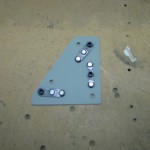
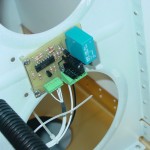
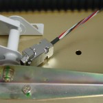
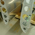
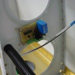
Also finished wiring the internal parts of the wings, trimming the wires to length and crimping on the connectors for the landing lights and the D-sub for the autopilot servo, and terminating the leads to the pitot heat control board.  I later realized that I have not yet run cable for the OAT sensors which will be installed in the right wing to feed the EFIS boxes.  I also epoxied some zip-tie bases to the underside of the seatback bulkhead for holding the headset jack wires, and installed the baggage light strip under there as well, using it’s built-in adhesive strip.

Pitot heat controller wired Landing light connectors Autopilot servo connector

Neighbor Jeff stopped by to check on the progress; it’s been awhile since he’s seen the project.  People who see it now say it looks like an airplane.

Hours: 5.2 | Posted in Electrical, Skin Panels | Comments Off
29th August 2010

Back to the wings

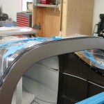
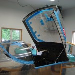
A collection of things happening in the shop today.  First thing up, finish the canopy sealing.  The excess Sikaflex was rubbed off the exterior of the top skin and the inside of the rear window and canopy (from gluing the spacer gaps), followed by removal of the rear window spacers and insertion of sealant into those gaps.  Smoothed those over with tongue depressors and all looks good.  Some canopy work remains, of course, but the plexi is in place (which was the big summer goal).
Final sealant applied to roll bar Canopy is nearly finished

Before the gear can be put on the fuselage, the wings need to be fit, which was skipped earlier in order to get the canopy done in the warmth of summer.  In order to do that , the wings will need to be finished (bottom skins riveted on, which means that they must be wired and plumbed).  Out came bottom wing skins, which needed edge deburring and a few dimples made.  After those were done, the skins were etched for priming along with the rear baggage wall; unfortunately it was too windy to prime until after dark, so that’ll have to wait for another day.

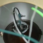
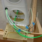
Cleaned up the inside of the wings, which had naturally collected a layer of shop dust and spiderwebs, and set about running the various wires and tubes for the in-wing systems (pitot heat, lights, strobes, AOA, and autopilot).  Everything except the pitot tube was run inside the corrugated conduit which was installed during the wing build.  A hole was drilled in the conduit near the aileron bellcranks, to permit wires to emerge for autopilot and pitot heat; once these wires are in position, some RTV can be used there to prevent any chafing on the conduit edge.  The control module for the heated pitot was installed on the rib near the bellcrank inspection hole, which should allow access to hook up the pitot wires later on.  The pitot tube was secured underneath the aileron bellcrank with an adel clamp to prevent interference or chafing.  All the wiring and tube will terminate at the wing root in connectors, to allow the wings and fuselage to be fully wired in the shop, and easily joined at the airport later on.

Inboard end left wing Wing wiring/plumbing outboard end Pitot control module installed Pitot line secured under bellcrank

Hours: 5.2 | Posted in Canopy & Frame, Electrical, Skin Panels | Comments Off