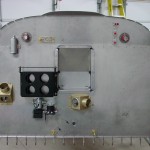
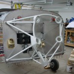
28th April 2011

Exhausted

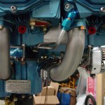
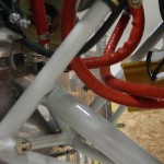
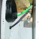
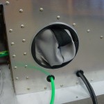
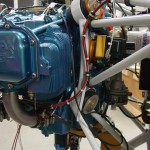
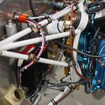
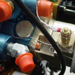
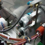
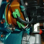
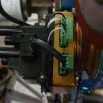
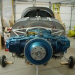
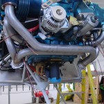
The Vetterman crossover exhaust (with mufflers) arrived this morning.  After unpacking, I took it out to test-fit.  The flanges fit right up, and it looks like there will be sufficient clearance from all the hoses, wires, and such.  It’s not really bolted on yet, just held in place with a few bolts.  Not sure if it’s best to fit the cowling with or without it on, and it will need to come off to be drilled for the EGT probes, anyway.

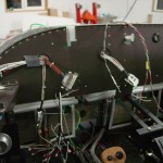
Messed around with the control cables for the throttle and mixture, temporarily attaching them to the fuel servo.  There is a long distance from the end of the cable to the fixture nuts, so I’ll need to move both of the control brackets one more hole aft before creating the brackets to hold the cables.  Drilled out the mounting hole for the purge cable and fit that to the panel; that one still needs to have the FW eyeball installed (as does the alternate air cable, when that’s ready…)

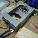
Pulled out the cowling again and started looking at how to fit it.  I have a 2×2 sheet of .063, which will probably make the camloc strips, but it’ll need to be done in 3 pieces as the dimension to span is around 53″.

The verdict on the AFS/VP-X amps & volts is that it’s not currently supported to source the gage reading from the VP-X datastream.  Hopefully they’ll consider adding this in a future software update; it seems a bit silly to have a current shunt (and associated cables and connectors) when the data is already there.  For now, I disabled display of the ammeter.

Hours: 1.5 | Posted in Engine | Comments Off

27th April 2011

It must be the weather

It was interesting to me that two things appeared in the last couple days that found me where I’m at: an article in EAA’s homebuilding e-newsletter, and parts of a thread on VAF, both around with what the article named “Project Paralysis.”  It must be the weather–for most of the month, it’s been gray, gloomy, raining/snowing, and cold (running 10+ degrees below average; we had snow yesterday for a bit).  March was exciting, and I put in far more hours than expected (nearly 80), but April has been a downer.  Only 25 hours, and the motivation to head to the shop in the evenings hasn’t really been there.  Work is heading into the busy spring season, which will last the next 5+ weeks, but I don’t think it carries the sole blame for the lack of energy.  Must be the weather…here’s hoping the snow stops soon.  On the bright side, I’ve spent some good time with Allison talking/dreaming/scheming about plans for the summer and beyond.

This week, though, has been looking up.  Lots of boxes arriving, the UPS man has been here every morning.  Engine hoses, control cables, and my AFS screen are here, and the Vetterman exhaust should be in tomorrow.  I’ve been reading up on fitting the cowl (among others, a good thread by Brantel on fitting the pink cowl, and a new one on baffles, plus DanH’s highly informative and well-illustrated fiberglass tips), which seems like a logical next step.  I need to pick up or dig up some PVC pipe to use as a stand-in for the prop spacer, and fit the camloc strips first.

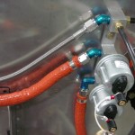
The task list for tonight was simple, and easy to motivate with new and exciting parts: test-fit the hoses, and fire up the EFIS.  All the engine hoses seem to fit well (though the oil cooler is not yet installed, so those can’t be fit yet).  I got these from Tom at TS Flightlines, who was easy to work with and fast getting them out.

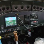
The EFIS screen (AFS 4500-EE), having already wired all the harnesses during the panel install, slid right into the tray and powered up.  Spent some time going through the menus, configuring serial ports and such.  Two oddities I noticed (1. the master warn light never illuminated when it should, but did when the screen was powered off, and 2. the screen always powered on when the master was turned on, even though the avionics bus wasn’t on), turned out to be related, and a simple fix: I had inadvertantly inserted the pin for the master warn light into the wrong hole, which caused it to be hooked up to the backup power input.  It was getting power on that backup input when the master went on (since the annunciator power is always on), and booting up (and illuminating the light).  Once primary power was applied, it stopped using that backup input, and the light went out.  Moving it to the correct pin solved both problems.

Allison came out and I put her seat in, and we sat in the plane looking at the panel.  Tested that the audio out of the AFS works, and it talks to everything hooked to it: VP-X control, transponder gets altitude, a finger in the CO detector pops up a readout of O2 saturation and heartrate, and it sees data from the GPS.  I posted a message on the AFS forum about the volt and amps gages…I had been under the impression they would take their readings from the VP-X datafeed, but that doesn’t seem to be the case, or at least I can’t find it in the menus.  The voltmeter is using the internal sensor of the AFS (not a big deal, it matches the VP-X within 0.1 volt, but of course reads 0 when the avionics master is off), and the ammeter just reads 0, since I didn’t install the shunt (since I thought it would come from the VP-X).  Both values are displayed on the VP status page, but it would be nice to have them as gages in the display, and be able to alert on them.

Hours: 2.0 | Posted in Electrical, Engine | Comments Off

12th April 2011

Oil cooler test

I wanted to get the order put in for all the FWF hoses at once, and to do so, I needed to identify what hoses were needed for the oil cooler hookup.  This, in turn, required test-fitting the aft left portion of the engine baffles.  The good news is that I was able to figure out what hose lengths would work, and I’ve sent that off to the guy who’ll be making the hoses.  I also determined that the hose routing should work with the wire runs and such I’ve already mounted.  I did move one adel clamp to provide some additional clearance at the lower corner of the cooler.

Also received the package from Van’s today with the AeroLED lights — these things are bright!

Hours: 1.5 | Posted in Engine | Comments Off

10th April 2011

Random pieces

Long week with no work on the project; the busy season has begun at the office.  Some positive news on the financial picture front this week though, so I at least ordered a bunch of pieces that I’ve been holding off on, for upcoming installation (lights, exhaust, APRS stuff, ELT, oil cooler, etc).

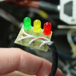
Got a few things done and half-done today; starting off with the wiring for the pitot indicator.  I bought my Gretz pitot secondhand, and it didn’t include the indicator board, since the previous owner had installed it in his plane.  No problem, it’s just a few LED’s with appropriate resistors, but I hadn’t yet taken the time to measure the voltage, find the right resistors, and build the board.  I used a chunk from a leftover piece of prototyping board, trimmed to fit the necessary components.  I also put a 4-pin Molex connector on it, for ease of connection (the soldering could happen on the bench, rather than in the plane) and service.  A matching connector on the wire behind the panel, and we’re in business.  I connected up the pitot for testing, and rolled the wing cart over to plug into the fuselage.  Power on, and everything looks good: the lights indicate as they should, the heater cycles, and the tube tip gets hot.  While I had the left wing hooked up, I checked the function of the leading edge light and made some minor programming changes in the VP-X (renaming some pins).

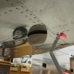
Installed a standard NMO mount and the Antenex Phantom Elite antenna I ordered, which will be for the APRS installation.  I also ordered the new MicroTrak RTG FA from Byonics, which should arrive next week.  The antenna is mounted halfway between the comm antennas and the transponder antenna.  I could have mounted it aft of the transponder antenna instead, but since the VOR/Loc antenna location is at the tail end, I thought it better to keep the APRS more distant, since the APRS and Nav signals are on nearby frequencies, while the transponder is removed by several hundred MHz.

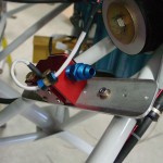
Thanks to some photos helpfully posted on a VAF thread, I decided to figure out the installation of the fuel flow sensor.  I fabricated a mounting plate from some scrap .125 bar stock, which attaches to a pair of engine mount tubes via Adel clamps.  The sensor mounts to the plate using it’s own 1/4″ mounting holes, for which I of course don’t have the correct length bolt (AN4-17A).  I also need to order the steel nipples for the in and out of the sensor; the sensor ports are 1/4″ NPT, rather than the 1/8″ commonly associated with the -4 fluid lines, so that will require the “-4-4″ nipple, which is 1/4″ NPT to -4 flare.  I cut off the spade terminals on the sensor wires and fit a 3-pin Molex instead, then ran the harness wires to the sensor location and connected the two.  I also installed Adel clamps to strain-relief the wires both at the sensor and at the connector.  Since the mounting plate floats in space between the two engine mount tubes, it’ll be possible to wrap the entire assembly in a piece of firesleeve.

With the FF sensor located, I set about measuring for fuel lines, and re-checked all the ones I’d measured previously.  I have a list of 8 hoses that need to be made up now.  There are two more yet to be measured, for the oil cooler lines, which won’t be evident until the oil cooler arrives and is at least mocked up in place.  Plus, the brake lines, but at least those are already known lengths.  The steel oil cooler fittings will also need to be ordered.

Moving back inside, I experimented with various locations for the pitot/static manifolds.  Fabricated a bracket to mount both, one atop the other, and mounted it to the subpanel.  I need to pick up some longer #6 screws to mount the manifolds to the bracket, though.  Trimmed and inserted the pitot and static lines, and a pair of jumpers for EFIS 1.

Also spent time cleaning the shop, tossing/recycling the large pile of debris that had collected under the plane.  Storm season is here, and I need to get at least one vehicle inside when weather threatens (as it is this weekend).  I figured out that I can move the fuselage 90 degrees to the right and Allison’s car will tuck nicely under the tail.

Passed 1300 hours in this session.

Hours: 8.2 | Posted in Electrical, Engine, Plumbing | Comments Off

27th March 2011

Electrical loose ends and misc.

Worked on a laundry list of essentially small tasks, which filled up most of what turned out to be a fairly productive day.  I’m approaching the point where I need to order a bunch of stuff in order to continue installing things (like control cables, exhaust, FWF plumbing, and so on), but that’s likely to be delayed for a few months for finances, and it’s likely that if it’s delayed into May, it’ll be delayed until fall.  Oh well…perhaps the summer project will have to be tips, fairings, and wheelpants.

  • Finished programming the VP CU and testing electrical continuity and switching to all the devices which are installed.  Even plugged one wing in to check out the taxi light, and the wig-wag.  The VP config program, along with the Ethernet connection, is pretty slick.
  • Fabricated the attach point and pushrod for the flap position sensor; installed the sensor and adjusted the pushrod for appropriate travel.  Monkeyed around with the VP flap options, checking out the momentary feature which uses the pos’n sensor to run the flaps to pre-determined stops.
  • Fabricated and installed doublers for the comm antennas, which tie into the seat ribs for extra stability.  Terminated the L antenna coax and installed both antennas.
  • Terminated coax and installed the ADS-B antenna.
  • Installed the aileron pushrod boots.

  • Made up and installed a wire to tie the shields of the nav/strobe light cables to ground; per AeroLED’s recommendation, these are tied to airframe ground at the terminal block under the LH seat pan.
  • Installed a tiewrap base to secure the pilot stick grip connector, and secured it.

  • Bolted the throttle quadrant to the panel; both the quadrant and the panel now have added stability.  This is at least temporarily bolted in place, so I can get an accurate measurement for ordering control cables.
  • Swapped out Adel clamps on the center heater control cable, now that I have the correct size on hand.
  • Installed an Adel clamp on the parking brake bracket and adjusted the cable end to swing to the correct angles for open/closed.
  • Used a pair of Adel clamps to stand-off the parking brake cable from the LH fuel vent line.
  • Went on an Adel-clamping marathon FWF, establishing wire runs along the engine mount tubes and getting the sensor wires going in the appropriate directions.

  • Installed and safetied the oil temp sensor bushing w/crush gasket, and the oil temp sensor.  Wired the sensor.
  • Installed the fuel and oil pressure sensors on the sensor manifold, and wired both sensors.
  • Wired the manifold pressure sensor.

  • Wired both Pmags and secured the wires with heatshrink and Adel clamps.  Tested power to the Pmags; the LED’s lit up, so I’ll assume it’s good for now.  The install docs warn against doing much of anything without the ignition leads connected, so I didn’t put them in “run” position.  Tried to install EICad (the Pmag programming software) on my laptop, but the setup program fails; it may not like Windows 7.
  • Installed new lockwashers where a couple Pmag mounting nuts had been loosened for access or installation, and torqued.

  • Temporarily hooked up the power harness for the Reiff engine heater, and plugged it in for a test.  It gets warm pretty fast!  I know there isn’t much oil in the sump now to heat, but it had the engine case warm, and the cylinders warming, without much delay.
  • With the antennas, terminal strips, pushrod boots, etc. in, I shouldn’t need to get under the seat pans for awhile, but it will be nice to sit in the plane to program avionics and check things like rudder pedal location…temporarily installed the seat pans with a reduced number of screws.  I’m planning to use stainless button head hex screws and washers on these, so this was a good test of that plan–worked perfectly.  I should pick up a set of ball-end hex drivers for doing these in the future.  (Note to self: seat pans are reversed, the right one should be on top at the overlap…will reverse when next removed.)
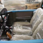
  • With the seat pans in, put the seats in (still wrapped in plastic; I’ll also need to pick up some towels or something to protect the seats on ingress/egress).  Climbed in and had a sit for a minute…looks like the rudder pedals will need to be at the most fwd position, which surprises me since I’m not terribly long of leg.  Might also try the seatback in the aft hinge, but I was pretty comfortable at the angle they were at in the middle hinge.

  • Tossed the charger on to top off the battery, as I’ve been running power for periods over the past few sessions of electrical install.

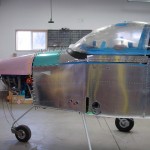
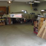
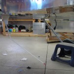
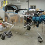
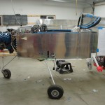
And a couple of “big picture” status shots for those who wonder what the plane actually looks like these days…

Hours: 9.3 | Posted in Electrical, Engine | Comments Off

12th March 2011

Panel and wiring

Started off working on the panel, by riveting the EFIS trays in place.  The design of the trays really helps stiffen up the panel, pretty much eliminating flex in the vertical, and the radio stack angles help as well.  Once the EFIS trays were riveted in, the panel was clamped to the bench and I started fitting the radio stack trays.  This was fairly easy, using a ruler, calipers, some wood blocks, duct tape, and a stack of popsicle sticks for fine adjustment.  Once the trays were clamped in position, the mounting holes were marked with a drill bit, center-punched, and drilled to size on the drill press.  Dug around for suitable screws to mount everything, and the SL-40 needs thin washers on either side, as it’s tray is just a bit narrower than the rest.  I aligned the 327 and SL-40 to the bottom of the panel cutout, and the audio panel to the top, and the resultant gap in the middle measured out at the right size for the 430…the miracle of CAD.  Finally, took it all apart to debur, prime, and rivet together.
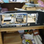
Once the panel was all riveted, I scrubbed the rivet rows with scotchbrite and slathered on a light coat of epoxy.  When it cures, I’ll sand it smooth, which should effectively make the rivet rows disappear when painted.  I wouldn’t have bothered with this, but there are a couple of extra holes that needed to be filled, because of the late discovery that the right rib would need to be moved.  Found that the epoxy takes awhile to cure, 10-15 hours according to the can (West Systems w/206 hardener).  Should be ready for sanding & paint tomorrow if I bring it inside overnight.

With the panel curing and unavailable for further work, I set upon other tasks…torqued the CHT sensors and put drip loops in their leads; this lead to fabricating and installing the starter cable, more adel clamps installed to hold that cable and give a place to tie the CHT’s to.  EGT’s will tie into the same place, but with no exhaust system, it’s hard to install those!  I’ve left the cable unattached at the starter end, to avoid inadvertant activation.
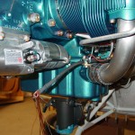
Finished installing the nutplates for the manifold pressure sensor, and bolted that in place.  Connected the silicone tubing from the sensor manifold to the sensor.  Filed down the center heat box cable eyeball to give it better grip on the cable, the finished installing that cable and terminated on the flapper arm.
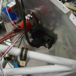
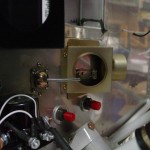
Started on installing the wiring for the AFS system, by running the magnetometer wires to the tailcone.  I hope I’ve got everything I need back there, because there is zero room left in the snap bushings at the rear spar bulkhead…  The only thing that is left to go aft of the main spar (except for all the connectors, of course) is the mic & phone lines, which won’t need to pass through the rear spar bulkhead, than goodness.  The magnetometer wires were just long enough to get where they need to go.

Those lines in, worked on the rest of the AFS wiring, putting in the engine monitor harness, after removing a bunch of pins from the connector, inputs such as amps, trim, and flap position, which will be supplied via the VP-X system.  Figured out which wire was which, and ran them to the approximate locations FWF.  Removed the pre-installed fuel level wires and replaced them with the ones already run in the airframe.  Switched the RPM input line to the electronic ignition pin, to connect with the Pmag.  Sensor harness done.  Next up, the main harnesses, running serial and audio wires in the right general directions, power & ground, and tying up the external inputs, as I don’t believe I have any uses for them at the moment.  I may just pull these from the connectors as well, and stash them aside with the wires I pulled from the EM harness, for later reinstallation when necessary.  Along with all this wiring, of course, goes the regular installation of bushings, grommets, tie bases, and so on, as and where necessary.

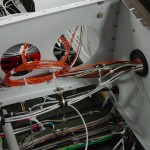
Discovered that the adel clamps I put in to secure the wire bundle on it’s vertical run from the tunnel to behind the panel, -14′s — which I assumed were oversized and would be swapped with something smaller once wiring was done — have reached their capacity.  I have 4 more wires to insert there (mic/phone lines), so they’ll probably need to be -15′s.  Of course, the next larger size I have from -14 is -18.  Sigh.
To do:

  • Print alternator wiring diagram
  • Print mockups of ARINC and ADS-B boxes for panel space arrangement
  • Find torque spec for oil temp sensor
  • Install starter cable boots, torque starter cable at contactor
  • Run additional ground wires for EFIS case grounds (18AWG)
Hours: 8.8 | Posted in Electrical, Engine | Comments Off

11th March 2011

Wire and clamps

Lots of parts new to the shop at the moment — recieved an order of adel clamps and misc. hardware from ACS, random stuff from McMaster, a crimper frim Digikey, and picked up a boxful of Garmin gear, plus a box of engine sensors, from SteinAir yesterday.  The AFS screen isn’t ready yet, hopefully in a month; word is that there’s a shortage of a part needed to build them.  I did get the tray, sensors, and all the harnesses, so there’s plenty to be done, and the screen should be able to pop right in when it’s ready.

Tonight I sorted a bunch of hardware into the bin racks for easy access later on; washers, nuts, nutplates, and so forth.  Also sorted the large collection of adel clamps I’ve amassed; pretty much fills a medium sized cardboard box.  (In case you’re wondering: the engine mount tubes are -12 and -14; you’ll want lots of those.)
With the adel clamps neatly organized, it was a good a time as any to start clamping things.  Worked on securing the alternator wiring and other wires that run around the engine mount.  There’ll be plenty more clamping to do as more wires get added to the FWF.  Put rubber grommets in the subpanel wiring harness holes, and ran the CHT/EGT harness through to start looking at wire run paths.

Worked on the panel and trays: modified the right edge of the EFIS 1 tray where it interlocks with the other one, drilled and countersunk the rivet holes to attach it to the panel.  Stripped part of the primer off the panel where I’ll use epoxy to smooth over the rivets around the trays and radio stack.  Primed the tray and back of the panel.

Pulled open the box of engine sensors and distributed them around: put the CHT’s in the cylinders finger-tight, the oil temp in its place.  Started work on mounting the manifold pressure sensor by drilling for nutplates, but called it a night when it was ready to rivet, since it was past midnight (think of the neighbors…)

Hours: 4.5 | Posted in Electrical, Engine | Comments Off

29th January 2011

Still more airframe wiring

First item on today’s list was the intake studs on the engine sump.  The ones that were on the engine as shipped were too short for the fuel servo and spacer/mount bracket, so Aero Sport Power sent out a set of longer ones.  The shorter ones were removed last week, and I picked up some high-temperature threadlocker (Permatex 27200) to put on the new ones, as recommended in the Airflow Performance install manual.  A few drops on the far end of the stud, a pair of nuts, and they were on and looking good.  Test-mounted the bracket and servo to make sure the length was good (it was), and to look at routings for control cables and fuel lines.  I’ll hold off on all that until I have an exhaust system, so as to not create any interference.  Also need to work out the location of the fuel flow transducer, which will go in the feed line between the servo and the spider which sits atop the engine.

Trying to get the airframe wiring (wiring that runs to various parts of the plane — as opposed to the panel wiring, which would connect the boxes on the panel and generally contained within the “avionics bay”, or engine wiring, which would run to the forward side of the firewall) generally wrapped up.  I have just about run out of space in the bushings that run through the center section, and still more wires to run, so it was time to add another bushing.  Evaluating various cable paths, I decided to put it under the fuel valve, to the right side, 2/3 of the way up the spar web, which would allow the wiring to run without chafing on fuel lines or interfering with the control column, and kept a good distance away from the other bushing holes.  A pilot hole a long #30, then a unibit made quick work of the holes, and I was able to use a 1/4″ drive handle to turn the unibit inside the center section to deburr the backside well.  Primer, then snap bushings.  (Tip: the snap bushings have a “ridge” on the inside diameter of the flange side that can be removed with a unibit, giving you an extra 1/16″ diameter…I’ve done this to all the bushings in the center section, to gain as much space as I could.)

More wires to run…2 coax lines for GPS antennas behind the rear window, plus power and ground for the ELT and APRS.  Need to look and see what the specified wire is for the magnetometer runs, as well as the GPS feed to the ELT/APRS (which will share a single feed line).  Also finished up the last of the wing wiring with the OAT, pitot heat, and landing/taxi light wires.  I tied up the bundles that run from the tunnel out to the wing roots, and sleeved the wires that pass out of the fuselage.  These will get CPC connectors on both sides, and the sleeving will be maintained all the way into the connector backshell.  I also put the straight union connectors on the AOA lines — the tails from the wing will pass into the fuselage, where they’ll be joined under the seat pan.  May do the same with the pitot line, but for now it’s run out the side.

Terminated the nav/strobe wires at the terminal block under the seat; this looks like it ought to work out alright, though were I to do it over, I would have put the snap bushing for the aft wires farther away from the terminal block.

Hours: 7.5 | Posted in Electrical, Engine, Plumbing | Comments Off

9th January 2011

Engine hanging

Before the engine could go on, there were a couple remaining items to take care of.  First, the nose gear had to be installed, and the wheel bearings greased.  I’ve packed bearings before, but these were difficult because they have a rubber seal on one side of the bearing, so the usual “pack it in ’till it comes out the other side” didn’t work out.  I packed it in as well as I could; the glob in my hand kept getting smaller, so it must have gone somewhere, but I’m not sure it was done perfectly, so I may revisit this wheel when I repack the mains prior to flight.  I also looked at the preload adjustment on the Matco axle; you’re supposed to tighten the preload ring until the bearings remain stationary to the axle while the wheel rotates.  I was able to get them to not rotate, but the wheel is very stiff…need to do more reading on this.

Item number two was to move the oil pressure fitting on the engine from the side port to the rear port.  I removed the fitting and the plug, and swapped them, installing the plug with EZ turn to the specified torque (which involved tracking down a copy of the Lycoming torque specs in Lycoming  publication SSP-1776).  The pressure fitting is just finger tight for the moment, until I determine if it ought to be a straight fitting instead (and if so, make one with a restrictor).  While I was monkeying with the engine, I also pre-installed the 90* fitting with the pressure tap on the fuel pump outlet.

With all that done, I took another look through my pre-engine hang list, and decided it was time.  I followed the “Illustrated Guide to Engine Hanging” and the procedure was pretty straightforward.  The trickiest part was the upper left bolt, as the nut is close enough to the pushrod tube that a box-end wrench gets trapped by the bolt when fully tightened, and the hole in the engine case is such that a box-end can’t get on the nut well.  I ground down a cheap box-end wrench so it was thinner along one edge, which let me remove it after the bolt was torqued.  Getting the cotter pins in was fun as well, and required some attention during the torquing process to see that the holes ended up in an accessible orientation.  In the end, no problems with the hang, and it’s looking good.

Once the engine was on, I couldn’t resist pulling out the fuel servo and test-fitting it. The AFP kit includes a nice anodized bracket/transition piece which fits between the servo and the sump, however, it is rather thick, and with it in place, the studs on the sump aren’t long enough to allow for the washer, lock washer, and nut.  In fact, they don’t even protrude through a single washer and nut.  Without the spacer in place, the throttle linkage hits the bottom of the sump, so clearly it needs to be there, and it also provides a mounting location for the control cable brackets.  I’ll have to look into the length issue.  Also need to look into how the airbox is intended to fit onto the servo; the parts are all there, but it’s not immediately obvious which way they’re all intended to go.  Lastly, I moved the throttle, mixture, and purge valve levers to the approximate locations they’ll need to be for the control cable attachments.

(Engine hang at ~1110 hours.)

Hours: 4.9 | Posted in Engine, Gear & Fairings | Comments Off

8th January 2011

Firewall sealing

Spent the morning at the Minnesota Wing meeting, talking and looking at a local RV-7 that was recently finished, which provided some good inspiration to move ahead on the FWF stuff; also had the change to talk to folks about some open questions: mufflers and heater boxes, seat heat switch location and wire routing, transition training, and so on.  Notes to self: the Torx screws on tips and hex-heads for interior panels look nice; heated seat wiring can be run out underneath the flap motor housing, and the cushion cables are long enough to reach; relays can go in the flap housing with switches on the crossbar (though they are hard to reach in flight, it cuts down on wiring run through the center section).

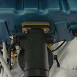
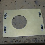
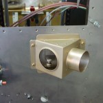
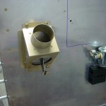
Back in the shop this afternoon, my goal was to get most of the firewall components installed and ready to hang the engine tomorrow.  Number one on the list was the heater boxes.  I chose to mount one in the center, feeding into the stock diffuser box; the second one is placed on the passenger side, far outboard.  I oriented that one with the outlet (which dumps the heated air when the valve is closed) pointing down, thinking that it would provide better airflow to the lower cowl exit.  This meant that the box had to be up the firewall some amount to allow room for the control cable to exit below it, so it ended up next to the battery.  Hopefully I don’t regret this, but I’ve been pondering it for several weeks and it was time to make a decision and get on with it.  I think in this location, it would be easy to add a flange on the cabin side if desired later, to direct the air from that vent to an eyeball or glareshield vent.  Everyone I talked to who has the muffler exhaust, or has flown a plane with it, is pleased with it and says that there is more than enough heat output, which will be a good thing.

I used a 2″ hole saw (buying the kit of quality hole saws was a good move, as I’ve had zero difficulty cutting the stainless) with the drill motor slowed down (regulator set ~35psi) to make the holes, and used the doubler for a template to drill the mounting holes.  I decided to use #8 screws rather than the #6 called for in the plans, mostly because I had truss-head #8 screws, and only countersunk #6 screws.  And, rather than using nuts on the backside, I put nutplates on the doubler to allow for easier one-man installation and future service.  These are the triangular heat boxes from Robbins Wings, which have a stainless steel hinge and flapper, with an aluminum box.  The theory being that if there was a fire, the box might melt away, but the flapper, being stainless, would remain to cover the 2″ hole in the firewall.  This is a variation on the all-stainless box, and seems good to me.  They include the doublers, and are set up for control cables on the engine side.

With the heat boxes in place, the next order of business was to install the firewall recess.  Besides removing the top skin, this meant mixing up the firewall sealant, Flamemaster CS 1900.  It is a two-part concoction, similar to Proseal, but part A is a very stiff paste and part B a thin liquid; it is difficult to mix, and remains very thick after mixing.  The data sheet indicated that it could be thinned for application, including brushing, by use of ketone solvents.  A little research told me that acetone is a basic ketone solvent (which saved me a trip to the store for MEK), and it took a lot of acetone to get it to a workable consistency.  Put it in a freezer bag for application, same as I did with the Proseal on the fuel tanks.  After wiping all the parts down with solvent as instructed, I ran a bead between the recess and the firewall and clecoed it in place.  I let that begin to set up while I sealed and installed both wiring pass-thrus, and sealed around the brake reservoir penetration.  Then I went back and riveted the recess in place, and sealed around the edges and in the seams and corners, filling the holes at the corners with a blob of sealant.  Cleaned up the mess and called it good.  Once the recess was in and the sealant had tacked, I bolted and torqued the battery box and heater boxes.  No pictures of the sealing process, because it’s hard to use the camera when your hands are covered in black goop.  The copius acetone thinning didn’t seem to affect it’s ability to cure, and it skins over fairly rapidly after dispensing.

Once the sealing was complete and cleaned up, I installed and clamped the outer firesleeve on the wiring passthrus, as it needs to be in place before the wires are run, and I didn’t want to forget it later and have to take all the wires out to install it.  (Like flaring tube without a B-nut, or soldering a connector without the backshell — not that I’ve ever done either of those…)

Engine mount is next…had to fit and remove a couple times to work on the nose gear bolt clearance, and I ended up putting a little “dent” in the firewall behind the gear leg to shift it aft and provide clearance for the bolt & nut.  I’ve read that this is not uncommon.  I also had to file a bit more off of the lower fuel pump nutplate to clear the lower mount tube, and I filled both nutplates with firewall sealant, since I’m not using them (this pump location is used only for carbureted engines; I wasn’t sure whether I would have carb or FI when I built the firewall, so I put the doubler & nutplates in).  As of now, the engine mount is bolted up, but not yet torqued, as I expect to need to remove it (along with the engine) one more time to drill and install all the cable and plumbing penetrations, once I figure out where they need to go.

Hours: 4.9 | Posted in Engine, Forward Fuselage | Comments Off