Panel and wiring
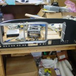
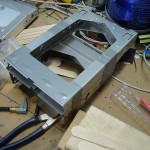
Hours: 8.8 | Posted in Electrical, EngineStarted off working on the panel, by riveting the EFIS trays in place. The design of the trays really helps stiffen up the panel, pretty much eliminating flex in the vertical, and the radio stack angles help as well. Once the EFIS trays were riveted in, the panel was clamped to the bench and I started fitting the radio stack trays. This was fairly easy, using a ruler, calipers, some wood blocks, duct tape, and a stack of popsicle sticks for fine adjustment. Once the trays were clamped in position, the mounting holes were marked with a drill bit, center-punched, and drilled to size on the drill press. Dug around for suitable screws to mount everything, and the SL-40 needs thin washers on either side, as it’s tray is just a bit narrower than the rest. I aligned the 327 and SL-40 to the bottom of the panel cutout, and the audio panel to the top, and the resultant gap in the middle measured out at the right size for the 430…the miracle of CAD. Finally, took it all apart to debur, prime, and rivet together.
Once the panel was all riveted, I scrubbed the rivet rows with scotchbrite and slathered on a light coat of epoxy. When it cures, I’ll sand it smooth, which should effectively make the rivet rows disappear when painted. I wouldn’t have bothered with this, but there are a couple of extra holes that needed to be filled, because of the late discovery that the right rib would need to be moved. Found that the epoxy takes awhile to cure, 10-15 hours according to the can (West Systems w/206 hardener). Should be ready for sanding & paint tomorrow if I bring it inside overnight.
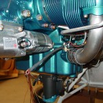
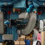
With the panel curing and unavailable for further work, I set upon other tasks…torqued the CHT sensors and put drip loops in their leads; this lead to fabricating and installing the starter cable, more adel clamps installed to hold that cable and give a place to tie the CHT’s to. EGT’s will tie into the same place, but with no exhaust system, it’s hard to install those! I’ve left the cable unattached at the starter end, to avoid inadvertant activation.
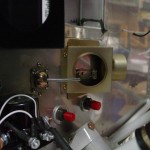
Finished installing the nutplates for the manifold pressure sensor, and bolted that in place. Connected the silicone tubing from the sensor manifold to the sensor. Filed down the center heat box cable eyeball to give it better grip on the cable, the finished installing that cable and terminated on the flapper arm.
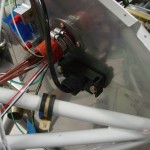
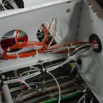
Started on installing the wiring for the AFS system, by running the magnetometer wires to the tailcone. I hope I’ve got everything I need back there, because there is zero room left in the snap bushings at the rear spar bulkhead… The only thing that is left to go aft of the main spar (except for all the connectors, of course) is the mic & phone lines, which won’t need to pass through the rear spar bulkhead, than goodness. The magnetometer wires were just long enough to get where they need to go.
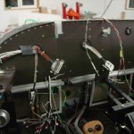
Those lines in, worked on the rest of the AFS wiring, putting in the engine monitor harness, after removing a bunch of pins from the connector, inputs such as amps, trim, and flap position, which will be supplied via the VP-X system. Figured out which wire was which, and ran them to the approximate locations FWF. Removed the pre-installed fuel level wires and replaced them with the ones already run in the airframe. Switched the RPM input line to the electronic ignition pin, to connect with the Pmag. Sensor harness done. Next up, the main harnesses, running serial and audio wires in the right general directions, power & ground, and tying up the external inputs, as I don’t believe I have any uses for them at the moment. I may just pull these from the connectors as well, and stash them aside with the wires I pulled from the EM harness, for later reinstallation when necessary. Along with all this wiring, of course, goes the regular installation of bushings, grommets, tie bases, and so on, as and where necessary.
Discovered that the adel clamps I put in to secure the wire bundle on it’s vertical run from the tunnel to behind the panel, -14′s — which I assumed were oversized and would be swapped with something smaller once wiring was done — have reached their capacity. I have 4 more wires to insert there (mic/phone lines), so they’ll probably need to be -15′s. Of course, the next larger size I have from -14 is -18. Sigh.
To do:
- Print alternator wiring diagram
- Print mockups of ARINC and ADS-B boxes for panel space arrangement
- Find torque spec for oil temp sensor
- Install starter cable boots, torque starter cable at contactor
- Run additional ground wires for EFIS case grounds (18AWG)
