26th July 2011

FWF loose ends

Worked on more engine-related stuff tonight:

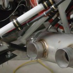
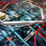
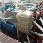
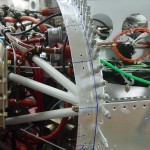
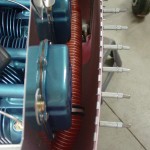
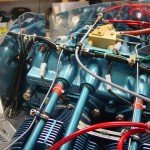
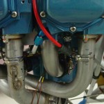
  • Finished up making and installing the exhaust hangers
  • Torqued and sealed the case bolts where the hangers bolt to
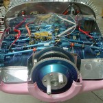
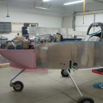
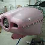
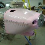
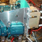
  • Test fit the lower cowl to check for exhaust clearance, and adjusted the left side a bit to gain more space
  • Rerouted the starter cable to get more clearance from one of the hanger tubes
  • Added an adel clamp to the purge return line alongside the battery box
  • Installed the hose portion of the breather; need to get some large alum. tubing for the lower portion
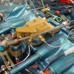
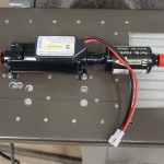
  • Drilled a hole for the fuel pump vent exit, bent a piece of -4 tube, and secured it (at least temporarily) to the engine mount
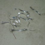
  • Cut a slot in the camlok strips to allow for insertion of the vertical hinge pins on the lower cowl


Hours: 3.6 | Posted in Engine | Comments Off

24th July 2011

Working the list

Started out by giving more attention to the HS/VS tips (the elevator/rudder tips don’t require so much work, and I’m glad for it).  Sanded the filler layer of micro I added yesterday, and got things looking relatively decent.  Spent some time reading on what the process is from here; it looks like there should be an epoxy sealcoat or three over the microed area, then a primer, and possibly another primer after that.  I’m reading much of what DanH has written over at VAF, and have found the specs for the PPG coatings used by many of the folks; have to see if there is a local supplier, or if it’ll be a mail-order operation.  DPLF is the basic primer, and K36 is the high-build primer/surfacer.  The finishing steps, as I understand them, are to brush or roll 3 layers of straight epoxy, then sand, shoot DPLF, sand/fill if necessary, then a light coat of DPLF and a coat or two of K36.  I don’t know if the K36 step is needed at this point, or if that’s something that’ll happen at paint prep time.  After sanding them up, I added a fillet of flox to the inside of each tip, to strengthen up the joint at the back.  Hopefully these will be done soon…

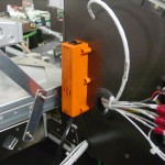
Next I tackled the pre-installation for the SD-8 backup alternator/dynamo.  I’ve installed the relay and capacitor, but haven’t bought the regulator or dynamo to save the $500 for the moment.  This is purely a backup device, so I don’t need it to get flying, but want to add it eventually.  I drew up a full-size paper mockup of the regulator so I could locate nutplates to secure it, and installed those.  Then, I installed all the wiring, and ran the lines which run to the regulator to a CPC connector mounted below where the regulator will go.  When I get the regulator, I’ll put a mating CPC on it, and it’ll be a simple matter of bolt in and plug in.  Also ran a loop of wire FWF and secured the excess length to the wire bundle along the upper engine mount tube, where it’ll stay until the installation of the dynamo.


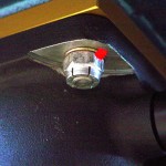
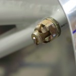
Started on the installation of exhaust mounts.  Tightening down the bolts on the ball joints to the specified 2-threads caused them to become rather tight, so I may need one length longer bolts there — not sure how tight or loose it’s supposed to be, but the install guide does say that it’s important they be able to flex, and recommends lubricating them regularly.  Got the right side hangers fit, and the left side marked and cut, before quitting time.

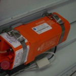
And, stuck the biennial registration sticker on the ELT.

Hours: 5.4 | Posted in Electrical, Engine, Wing & Tail Joins | Comments Off

7th July 2011

Tailcone camping

Received a couple supply orders this morning, from SteinAir and McMaster, so parts were on hand to complete a few tasks.

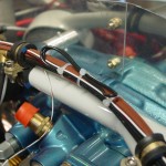
Installed the intake gaskets and bolted the fuel servo and spacer/bracket to the sump.  I bought some all-metal steel locknuts in 5/16-18, which is the thread on the long studs AeroSport sent to me.  I’ve installed the standard-height ones, but even with a thin washer, the threads are only flush with the bottom of the nut, rather than the usual 1-or-2-thread protrusion we want (though they do appear to be fully engaged; there’s just no excess).  I installed them for now, torqued and sealed, but will ask around to see if this is a real problem; if so, whether using shorter nuts (which I also bought) would be acceptable here, or if I’ll need to locate and install longer intake studs (ugh).  In other FWF news, torqued the engine mount bolts and installed cotter pins.
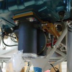
Installed the quick-connect fittings on EFIS 1, into which were installed the pitot and static tubes.  Blowing lightly in the pitot line at the wing root caused the airspeed to come alive, and capping the tube off cause it to hold steady, so the system within the fuselage appears to be tight.  Sucking lightly on a static port indicated a climb, so that’s good too, though that one isn’t guaranteed leak-free, as I wasn’t able to plug the opposite port and hold suction; that test will come later.
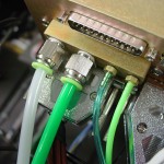
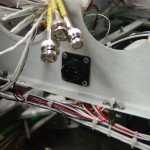
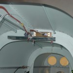
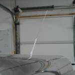
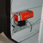
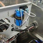
Moving toward finishing the ELT install, I drilled a hole in the aft top skin for the antenna, and fabricated a circular doubler to go inside, per the installation guide.  Routed a coax from the ELT to the antenna, secured and terminated.  Hint: a BNC connector doesn’t fit through the 1/2″ hole for the antenna, and if you install it with the coax pulled to the outside because it’s easier, you’ll have to cut it off and do it again, the hard way…don’t ask how I know.  Routed and secured most of the wiring around the ELT itself, though the wiring is not done yet.  Some fiddly soldering on a 4-pin DIN needs to be done to hook up the power and GPS signal (why they chose that awful connector, I don’t know…).  And, I need to terminate the RJ-11 ends, and of course my RJ crimper is in my toolbag at the office.
In the same area, installed a nutsert for the APRS box, and secured that along with it’s wiring.  Placed a couple ziptie bases along the wire run to the RS-232 service port and status indicator light and secured those wires, as well.  Still haven’t seen any pings from the APRS show up on the internet, though that’s not surprising as it’s been in the garage the entire time.  I might push it out someday and see if it’ll ping, but with the bottom-mounted antenna, I don’t really expect to see anything until she’s airborne.
And as long as I was working in the tailcone, I finished securing the wires that run along the floor, including the addition of a few ziptie bases.  Also removed the test-fit magnetometer mount, deburred and primed it so it can be riveted in place.  I see at least a couple more trips into the tailcone (mag/mount install, finish the ELT, install the elevator pushrod) in my future, but hopefully I’ll be done with that soon, at least for awhile.  Once you’ve got camp set up in there, it’s not so bad, but getting in and out is a bear…and even more fun when you get yourself inserted and then realize the tool you need is still on the bench.
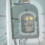
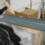
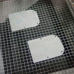
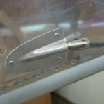
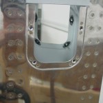
In keeping with the tailcone theme, but on the outside, I installed the rudder cable fairings that were prepped yeterday.  The night’s last act was to install the nutplates on the elevator horn inspection holes, then prep & prime the cover plates.
Checked the FAA registry tonight and saw that my N number is now showing as assigned, with the proper details of my airplane.  So, it appears my registration has been received.  I’ll laugh if the state tax people call up in the middle of the current government shutdown to ask for their pound of flesh…
Hours: 5.2 | Posted in Aft Fuselage, Electrical, Engine | Comments Off

4th July 2011

Slow day

Spent a good portion of time in the shop today, but didn’t accomplish a great deal, it seems.  I started the day with a list of what seemed like easy quick tasks, but in reality, I only checked off one thing.

The main order of business for the day was finishing the EGT/CHT wiring FWF.  Having installed or test-fit essentially everything in the area, I finished running the wire harness and sorted out which wire was which.  After creating service loops and trimming to length, the wires needed to be terminated, using the recommended method (crimp, flux, solder, heatshrink) from AFS.  I put heatshrink on each terminal, as they’re uninsulated; once the terminals were joined together, heatshrink went over that, then a larger piece of heatshrink to bundle the pair of wires for each probe together.  It should be secure and well-protected, yet still easy enough to cut away when a probe needs to be replaced.  Once everything was hooked up, I used a heat gun to check that the proper probe is wired to the proper location — the EGT’s are, but I wasn’t able to get the CHT’s to show on the display; not sure what’s going on there, although the EGT’s disappear below a certain point as well (100*, I think), so the CHT’s probably have similar logic and I just wasn’t able to heat them far enough given the larger thermal mass of the cylinders.

Other more minor tasks accomplished:

  • Fabricated, fit, and painted an angle brace to go between the panel and the subpanel, to eliminate a slight flex in the left side of the panel.  The brace ties into the EFIS 2 tray with a countersunk screw, and is fixed to the subpanel with a riveted clip.  Will install this tomorrow once the paint is dry.
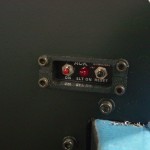
  • Installed the ELT remote to the panel, and attached the audio alert box to the subpanel.  The audio alert can be serviced without removal, since the cover unscrews from the base, but the remote will need to be removed again for installation of the battery.  There are actually three batteries in the ELT system — one in the ELT itself, one in the remote, and another in the audio alert box.  All except the ELT have to be procured by the builder.  I haven’t looked yet to see if they’re all good for 5 years like the ELT battery, or if more frequent replacement is required.
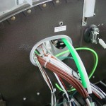
  • Since EFIS 1 was removed for access to fit the panel brace, I took the opportunity to enlarge the wiring hole behind it.  My initial hole was large enough for the requisite wires, but the bigger, oblong hole will remove the tight bend that a few of the wires had to take, and give more space for the pitot/static/AOA tubing.  Speaking of which, I found that I never ordered the fittings for the pitot/static connections to the EFIS.
  • Ran switched/dimmed power and ground to a plug at the subpanel, where the panel flood lights will connect.  These lights are mounted to the underside of the glareshield, which is part of the canopy, hence the need for a disconnect to allow canopy removal.

Hours: 7.1 | Posted in Electrical, Engine | Comments Off

3rd July 2011

Working the list

Worked on various things today, all generally related to FWF…
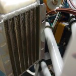
  • Measured for, built, and installed an angle brace for the oil cooler.  To avoid interference with injector lines, ignition wires, and purge valve cable, I tied it into the clip that was fabricated earlier for the purge valve cable.  This, as promised, stiffened up the oil cooler quite well.
  • Made up the tubing spacers which go between the flanges of the oil cooler to keep it from being deformed by the mounting bolts.  Installed spacers and cooler, after removing/reinstalling the aft left baffle to drill the bolt hole for the brace.
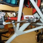
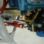
  • Worked through the engine control linkages FWF.  Drilled the mounting brackets for bolts and installed, torqued rod ends, and replaced temp fit bolts with proper length ones, torqued and sealed all fasteners.  Was going to install the fuel servo & bracket, but it seems I never ordered the proper nuts (5/16 coarse thread all-metal locknuts) to do so.
  • Unbolted the purge control cable and threaded it back into the cabin in order to install the eyeball passthru in the firewall.  Re-ran the cable, installed final bolts, torqued & sealed fasteners.
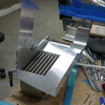
  • Riveted the left side heater air takeoff and screen to the baffle ramp.
  • Torqued and sealed the brake lines which run from the fuselage to the caliper.  At this point, the brake system is completely installed (except for fluid).
  • Looked at the exhaust system hanger clamps; it appeared that these could be adjusted on the pipe, but they are fixed in place with a welded pin.  I don’t understand how the hangers mount and where they run to, so will need to do some research.  The brackets seem to me like they’re facing the opposite direction of where they should (with the side ear facing outboard instead of in).
  • Worked on refitting the top cowling, which means trimming the baffles.  On this initial trim, the goal was to get them trimmed just far enough that the cowling can be fixed in place, not to get them to the final cut line.  It took several initial trims, then I spaced the top cowl up by clamping some wooden shims across both cowls, setting the top-to-bottom spacing consistent all around.  Then, cut a block and drilled a hole the same distance from one end as the space between the cowls.  Reaching inside with a sharpie through the hole in the block, I was able to slide it around and mark the contour of the cowl on the baffles, to establish a trim line.  (This method stolen from a VAF post)  Removed the top cowl and trimmed to the line, then a couple more re-fits to tweak, and it’s fitting well.  There will be more trimming ahead, for sure, but this was a good start.
  • In order to fit the top cowling, the camloc strips were reinstalled to the firewall edge, after having excess width trimmed from them (1/2″ trim, for a 2″ total width).  These are not yet drilled for the camlocs, so that 1/8″ clecoes can be used to secure the cowling to the strip.  The camlocs won’t be installed until the strips are installed, which isn’t until after the top skin is installed.  Chicken-and egg, yes…and there must come a point where the easy access under the top skin needs to be sacrificed in the name of getting the skin on so progress can be made, but not yet.
  • Neighbor Jeff and his brother stopped in to check out the progress.

And, crossed the 1400-hour mark tonight.

Hours: 8.2 | Posted in Cowling & Baffles, Engine, Plumbing | Comments Off

26th June 2011

Working the list

Worked on various little projects around the plane:

  • Finished install of cabin brake lines.  Torqued and marked.
  • Bolted rudder pedals in place.  Tried the middle holes, but with the seat put in, they’re too close for me, so moved them to the forward holes.
  • Messed with ignition leads to see how much too long they are (some are just right, others are several inches too long).
  • Cut pieces of screen for the second heater air takeoff, and the cabin fresh air vents.  Installed the vent screens between the scoop and the duct.  RTV’d the heater takeoff screen and clecoed the flange in place to cure; this’ll get riveted next time.
  • Played with routing for the left heater feed, which comes off the baffle inlet ramp.  Discovered that there is enough room between engine and cowling to run the SCAT along the bottom of the valve covers with adel clamps.  Will need longer screws to allow attachment of things like these clamps, and ignition wires, to the valve cover screws.
  • Fabricated and installed a bracket for the purge valve cable.
  • Installed new lockwashers, torqued and marked the engine case bolts along the top that were removed for installation of baffles & brackets.
  • Figured out how to install the Reiff preheater power harness along the top of the engine, and did so.  Ran the cable to the sump heaters through the same grommet as the fuel supply to the spider.
  • Installed clamps to secure the transducer-spider fuel hose.
  • Started work on finishing up the engine side of the thermocouple wiring.  I’m planning to leave these wires long and double them back, leaving plenty of extra length, as they would be a pain to replace in the event that one needed to be trimmed and no extra length available.

Hours: 5.5 | Posted in Engine, Plumbing | Comments Off

23rd June 2011

Engine fiddling

More work on FWF stuff today…routing the purge return line behind the baffles, then re-routing it to clear the oil filler tube.  Reworked the CHT/EGT wires on both sides to clear other items like the purge line, purge control, and oil cooler hoses.  Fit the oil cooler hoses to make sure everything had clearance.  Installed another fistful of adel clamps. Ran the purge control cable through the firewall and baffles.

Updated the FWF to-do list, but most of the components are in place now; much will be removed & reinstalled, but at least things are fitting together.

Brake lines and harnesses have arrived.

Hours: 2.8 | Posted in Engine | Comments Off

10th June 2011

Bouncing around

Now that work has settled down for the summer (127 hours in the last two weeks…), I’m trying to get back into the swing of working in the shop.  Took the day off work and bounced around on a few little things…

  • Finished drilling the hinges to the cowling and clecoed in place; test-fit the cowl and spinner backplate.
  • Fabricated a mounting tray for the AFS magnetometers, one bulkhead behind the baggage wall.  Installed the D-sub connectors and tested that the EFIS was talking to the magnetometer, which it was.  Clecoed everything in place for now; will need to rivet the tray in place, and pick up some brass screws for mounting the sensor itself.
  • Temporarily put in the lower spark plugs and attached the plug wires, so I could see where clearance would be needed in order to…
  • Drilled and installed the EGT probes to the exhaust pipes.  Fit the mufflers to the crossover pipes and held them up with bungees for now.
  • Removed the too-short mixture cable and replaced it with the new, longer one (48″) that arrived.  Fabricated a new bracket to secure the cabin ends of the control cables, and adjusted the linkages for proper throw on the quadrant and the fuel servo.
  • Started work on the rear left engine baffle where the oil cooler attaches.  Fabricated a reinforcing angle for the baffle corner to avert vibration cracking, and a thicker doubler plate for the cooler itself.  Once the cooler was located on the baffle, trimmed away a portion of the aft flange on the cooler to provide clearance from the engine mount tube.
  • Remade the fuel pump mount piece to accommodate the new version of the Andair fuel pump, which mounts a bit differently due to the now-integrated controller design.  The new mount is actually simpler; the overall pump length appears to be the same, so no adjustment of fuel lines will be needed.

Hours: 10.4 | Posted in Cowling & Baffles, Electrical, Engine | Comments Off

21st May 2011

Cowling

Spent a bit of time fussing with the control cables again.  I didn’t come up with a bracket solution that satisfied me, because the too-short mixture cable would need it’s bracket a couple inches closer to the firewall than the throttle.  The extender wouldn’t solve that, just make it reach the lever.  So, I guess I’ll order a longer custom cable, wait for it, and get it in right; then sell the short one to someone who can use it.  Also, more aluminum angle to redo the bracketry.

Cut the side hinges and hinge shims that will hold the lower cowling, and drilled them to the firewall.  Marked and cut the slot in the cowling for the gear leg.  Cleaned up the fiberglass on the backside of the nose flanges and refit the cowls together.  Clecoed the top cowl back on the plane, then put the bottom cowl on via the two clecoes in the nose, and a cargo strap under the rear portion.  The fuselage end seems like it will fit decently, but the nose doesn’t hold alignment with the spinner backplate — the gap at the top right side is 1/4″, and the lower left is 1/2″.  This might close up a bit with the rest of the fitting, but it looks like a load of filler will be required.  (Apparently this is not uncommon.)

Hours: 4.5 | Posted in Canopy & Frame, Engine | Comments Off

19th May 2011

Controlling

Spent a bunch of time working on engine controls today.  Figured out and fabricated brackets for the throttle and mixture controls, and temporarily installed, along with the cables, to test fit and function.  Trimmed the AFP brackets to match and provide clearance from the engine mounts.  Had to adjust the angle of the mixture arm, and use the shorter hole on the throttle arm, for the cable throws to work out with the throttle quadrant.  Extra holes for more throw also had to be put in the quadrant levers, a common item.  The throttle lever doesn’t have as long of a throw as I’d like (1/4-3/8 each end remaining), but it’s perfectly workable.  Couldn’t hook up the mixture at the quadrant end, as the cable is just a bit too short…aargh.  Will have to order one of the threaded extenders from Spruce, way cheaper than a new custom cable.

Put a rod end on the purge valve…still need to engineer that bracketry and FW passthru.  Also swapped out the bolts in the nosegear fork for longer ones with spacers, which give a better grip for the towbar to hook on to.

Hours: 6.0 | Posted in Engine | Comments Off