29th December 2011

Cover your tail

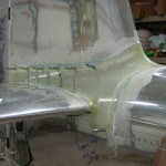
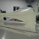
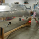
Trying to get the plane to the point where the tail feathers can be removed and stored, to allow more garage parking.

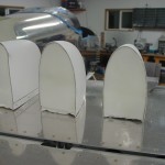
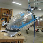
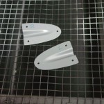
Fit the stock empennage fairing as best I could, which is essentially a ton of on-mark-off-sand-repeat, until it gets close.  Then I marked some final trim lines and sanded it back to there. Taped in place and carefully drilled #40 through the fairing into the open holes in the metal.

Next, to fill the little gaps that remain…  Taped up the metal surfaces and waxed them, and mixed up a batch of epoxy with micro and cabosil, slathered it on the inside of the fairing edges, and clecoed the fairing in place.  The idea is that the micro will fill the gap; once it’s cured, the fairing can be removed and the edges sanded pretty, then the rest of the finishing process can go on.

(Update: 55* in the shop is clearly not enough for efficient fiberglassing; the fairing took 4 days to set up completely, and that’s after pulling it off and bringing it in the house to sit.)

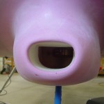
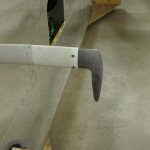
Also trimmed the layup on the cowling intake snout, and shaped it to be even with the intake.

Hours: 2.8 | Posted in Cowling & Baffles, Wing & Tail Joins | Comments Off

8th August 2011

More FWF, and flying again

Trimmed the excess from the aft end of the inlet duct, then chipped away the foam and the micro that held it in.  Sanded the inside down, and test-fit it back to the plane to see how it turned out — quite well, actually; the duct lines right up with the airbox.  Eventually, I’ll trim 1/2″ or so off the front of the airbox and attach airseal fabric.  Laid up one ply of 3″ glass tape around the duct on the inside of the cowl to add strength and thickness.  Once that cures, I’ll sand down the excess fabric sticking out the front and shape the nose of the inlet.

While I had the bottom cowl on, fit the top cowl to check fit of the airseal fabric; looking good so far.  I curved it over and added some paperclips to try and train the fabric to bend in the correct direction.  Tied up the engine heater wires behind the sump, torqued the baffle screw behind the dipstick tube, then installed & safetied the dipstick tube.  Plugged in the engine heater and verified it was still functional.


Finally made it to the airport yesterday to go flying with my CFI and get current again.  It came back better than I expected, and he was satisfied enough to sign off on my flight review, which was due at the end of the month.  That stamp says I’m basically safe…now the task is to fly enough to get proficient and fly accurately, then I’ll set up some transition training with one of the CFI’s who does RV-specific training, in preparation for getting this thing off the ground someday.

Milestone: crossed 1500 hours logged on the project tonight.

Hours: 1.9 | Posted in Cowling & Baffles, Engine | Comments Off

6th August 2011

Fiberglass & baffles

A very fiberglassy day, once again.  Also did a bunch of (more) reading on what primers and other coatings are required/recommended for finishing the glass parts.  I’ve identified the list that I would need if I were doing prep for parts that would be painted now/soon (PPG DPLF, followed by K36 or K38) — the part I need to sort out still is whether that is an acceptable stopping place for a plane that likely will not be painted for several years, or if some other coating/sealer/etc needs to be put on top.  I found that the K36 can be mixed either as a primer/surfacer, or as a sealer, where a base or clear component is added; perhaps that’s a good final step.

So, today’s work…sanded the epoxy coat on the HS/VS tips — that stuff is hard.  Which is as intended, really…but I was still surprised at the amount of work it took to sand.  These are now ready for the priming/finishing steps.  I need to get the rest of the empennage tips to this stage as well, then I’ll have a go with whatever process I settle on.

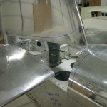
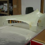
The next big job was to create the union between the lower cowl and the airbox.  Firstly, the front snout of the airbox needed to be trimmed back sufficiently to give clearance for the cowl to drop down vertically, so it can be removed with the prop in place.  This took several on-off-trim-test cycles with the lower cowl; I put the top plate of the box on the servo and trimmed that to fit, then trimmed the fiberglass bowl once the last trim point had been established.  I cut a hole through the middle of the foam blocks attached yesterday with a hole saw, then used files to work it out to the necessary size and shape.  During this process, I discovered that the epoxy I used yesterday to glue the two pieces of foam together was too hard for the job; the rear foam piece cracked off when the hole saw hit the layer of hard epoxy.  So, I made some measurements and fit another piece of foam to the aft side, using contact cement and a screw in each corner because I’m impatient and didn’t want to wait for it to set up.  That worked out, and I was able to shape a nice transition to the airbox.
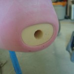
  

With the transition duct mold done, I had to do a layup to form the actual duct.  Wetting out the cloth (2 layers of the Rutan bid) was easy, putting it in place inside the duct, and getting it to stay there, was another story, but I emerged victorious, if a bit sticky.  To finish off the inside, I cut another piece of cloth, some lighter, tighter weave stuff I got, and laid that up as the final inside layer, which should leave it a bit easier to finish than the relatively coarse cloth.  I secured this all in position and left it to cure.  Later in the day, I trimmed the long excess and brushed a layer of epoxy on the inside, as the first step toward finishing.  Sanding inside that duct will be fun…  Tomorrow, assuming it’s set up enough, I’ll remove the foam and lay up another layer or two of cloth around the outside of the duct to securely fix it to the cowl.
 

Spent a bit of time cleaning up the shop, stuffing the trash pile in the corner into the garbage can and sweeping, before moving to the next task.

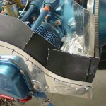
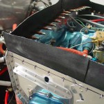
I decided to tackle cutting and fitting the airseal fabric on the engine baffles.  Started by making templates of all the baffle tops from cardboard, then cutting 3″ wide pieces of fabric matching those curves.  Laid out a rivet pattern on both side baffles, and drilled/deburred.  Taped the fabric in place and marked the holes, then drilled them in the fabric on the bench–the fabric is tough to drill, and didn’t drill well in place.  Even on the bench, it didn’t really drill, just poked a hole through.  Some have had luck here with leather punches, though I can get clecoes and rivets through the holes, so I don’t know how critical that would be.

The side baffles are in two pieces, to match the fore/aft split in the baffles.  I made nice curved pieces for the front segment, but they needed to be cut once in place in order for the fabric to bend over properly.  One cut overlaps itself, but the other opens up a gap, so I made a gap filler piece for each side, as well.  The aft segment, which came next, is also in two pieces, and the right side is captured between the baffle itself and the bracket which is bolted to the engine case.  Laying the top cowl on, it seems like these will work.  I need to see what’s needed for adhesive when affixing these — I bought some Pliobond earlier, but for these which are riveted, perhaps just red RTV is the thing to do.  I have not yet dealt with the front baffle, since it needs additional trimming and figuring out the interface to the top cowl.
  

Also need to sort out how the airseal fabric works at the front of the airbox; it appears that it’s riveted to the outside of the airbox, and seals as best it can around the outside of the cowling duct, not the inside.  I made the second piece of foam the right thickness so that the foam very nearly touches the opening of the FAB as currently trimmed, and I’ll trim the fiberglass of the duct to that point before removing the foam, so that obtaining the correct gap between cowl duct and FAB will be an easy task of measure and trim.
Hours: 9.2 | Posted in Cowling & Baffles, Wing & Tail Joins | Comments Off

5th August 2011

Fiberglass, mostly

More work on the fiberglass stuff…

  • Trimmed yesterday’s layup on the FAB; spread some flox/epoxy into the gap, and added another ply of glass on the inside.
  • Scraped and sanded the epoxy runs off the HS/VS tips; the epoxy isn’t fully cured yet so will wait until later to sand, when it’s harder.
  • Did a little cleanup on the empennage fairing, scraping off the unidentified brown goo splotches from the factory.
  • Tacked the foam block into the cowling snout.


And a bit of non-fiberglass stuff for sanity…

  • Torqued & sealed the fuel hoses at the flow transducer; FWF fuel system now complete.
  • Torqued & sealed the oil cooler lines; oil system now complete.
  • Deburred & dimpled the flanges of everything subpanel & forward…moving toward riveting the top skin.  Also had to remove the canopy pin mechanism, which will be fun to reinstall from under the panel while laying upside down…
  • Removed the camloc strips, deburred and dimpled the attach holes.
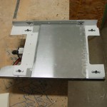
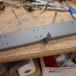
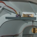
  • Cut a sheet of .020 and bent an angle into the edges, then fit it to the bottom of the fuel pump mounting plate.  Since this piece has a bunch of nutplates on the bottom of it, and many tubes & wires run beneath it, I decided that having a sheet in there would be a good idea to prevent any possible chafing (there is clearance between the plate and the bundles, but just in case, vibration and all that…).  This looks like it will do the job nicely.  It’s tacked to the mounting plate with a blob of Goop at each corner, and one in the center.


Doing some evening reading and working up a list for tomorrow, when I’ll again ignore all the other work that needs to be done to spend the day in the shop.

Hours: 3.4 | Posted in Cowling & Baffles, Engine, Wing & Tail Joins | Comments Off

4th August 2011

Fiberglass up and wait

Long week of work at work, and haven’t really had/taken time to work on the plane.  Looks like flying this weekend will be a bust due to the schedule at the FBO.  Off to the shop tonight to make some way on a bit of fiberglass work; this gets annoying because you can only do so much before you have to put it down and let it sit until the epoxy is cured.

  • Laid up 2 plies of glass at 45* to each other on the FAB split.  I’ll let this cure, then add more glass to the inside of the box.
  • Brushed on a coat of epoxy over the shaped/sanded micro on the elevator & rudder tips.
  • Sanded on the upper cowl inlet ramps until my arm wore out, smoothing the micro that was applied earlier.
  • Added a small layup of a couple plies of fabric on the inside of the emp fairing, the top aft side where it is torn (came out of the box that way).
  • Filed a bevel on the inside of the air intake snout, the first step of creating the duct that routes the air into the FAB.
  • Cut the supplied foam block from the FAB kit in half and glued the two halves together, in prep for fitting it to the cowl snout and FAB.
  • Went back to the shop later in the evening and put down another coat of epoxy on the elevator/rudder tips.

Hours: 2.1 | Posted in Canopy & Frame, Wing & Tail Joins | Comments Off

30th July 2011

Paperclip trick

Crimped a ring terminal to the buss end of the SD-8 power wire, and secured it to the VP-X stud with the main buss feed.  Verified proper operation of the SD-8 relay.  Loosened the capacitor and relay to allow bucking bar access above them for riveting the top skin.

Back to baffles for a bit; set up a row of paperclips around the sealing edge and put the cowling on; this pushes the paperclips down and reveals the spacing between the baffle edge and the cowl.  Once the cowl is removed, I marked a line 1/2″ down from the top of the paperclips, and used that as a guide to trim the baffles, aiming for the specified 3/8-1/2″ gap.  Rough cut with snips, cleaned up with files, finished with scotchbrite in the die grinder.  Refitting of the cowl revealed a couple small areas that may need a wee bit more trimming or a change in contour, but that’s easy enough to deal with.  Should be ready to cut airseal fabric soon.

I’ve slowly been adding ignition wires as time goes by, so I decided to put the rest of them in, and start work on tying them up.  I sorted out the various lengths and determined which is intended to go where, then started working from the spark plugs aft.  Swapped around some baffle/valve cover screws to get adel clamps installed on the lower screw of each valve cover, to hold the bottom plug wires.  I’m making spacers to secure adjacent wires with zipties and short pieces of silicone tube left over from the manifold pressure plumbing, similar to what’s shown in the Pmag docs.


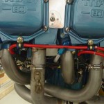
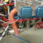
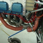
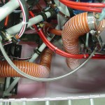
Also started work on the heater SCAT tubing, and got most of that routing sorted out and tube secured.

Hours: 4.1 | Posted in Cowling & Baffles, Electrical, Engine | Comments Off

28th July 2011

Three little things

Oshkosh week…I’ve been listening to LiveATC all week at my desk, with the flightline webcams running in another window.

Knocked a few more small items off the list tonight:

  • Loaded the latest software update from AFS on the EFIS.  The biggest new feature in this release is multi-leg flight planning, but I couldn’t play with that since the GPS isn’t connected up at the moment, so it doesn’t know where it is.
  • Did an initial trim of the forward baffles to match the curve of the inlet ramps, just enough to get the cowling on.  Next step here will be the paperclip trim.
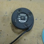
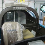
  • Cleaned the inside of the canopy using some stuff I got from Spruce called “210 Plastic Cleaner”.  I went a little panicky after the adhesive overspray incident, and ordered too many different things for cleaning, polishing and repairing scratches…the second thing I tried took the light fog right off.  (The first one, Permatex Plastic Cleaner, had a gummed up trigger and wouldn’t spray, so I wasn’t able to try it out.)  With the stock I have now, I ought to be covered on canopy cleaning for awhile…
Hours: 1.5 | Posted in Canopy & Frame, Cowling & Baffles, Electrical | Comments Off

9th July 2011

Canopy miscellany

Terminated the lighting wires that emerge from the underside of the canopy structure in a mating plug to the one installed on the subpanel the other day, and covered the loop with nylon sleeving for chafe protection.  Drilled a hole in the center of the glareshield to pass the GPS cable through.  Unpinned the  puck GPS cable from the DB9 connector, so it can be passed through the canopy hole when ready, and put a snap bushing on the cable. Two cables will come from the canopy, the panel floodlight and the GPS, both of which have a disconnect on the subpanel.

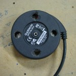
Also removed the magnets from the bottom of the GPS puck, and filled the holes with RTV to re-seal the casing, since with the magnets removed, you can see the sensor board and wires inside the unit.  Temporarily reconnected the GPS to the EFIS to verify that nothing was damaged during magnet removal; all appears functional.

Soldered a 3.5mm jack on the end of the cable that’s connected to the passenger phones line of the audio panel, and installed that jack into the bottom flange of the instrument panel, over on the passenger side.  I wired this up to provide a convenient place to tap into the intercom/radio audio with an audio or video recorder.  All audio wiring is now complete.

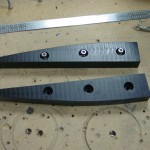
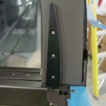
Worked with the block of black Delrin I ordered to fabricate and install the canopy closure guides.  The idea is that these low-friction guideblocks will capture the latch fingers as the canopy lowers, then align them properly with the holes they must pass through.  By providing a mechanical means for alignment (rather than relying on a human to guide it), the hope is that the possibility of cracked canopy corners or beat-up latch plates will be reduced.  This is a fairly common addition, it seems.

I started with a block of Delrin from McMaster, 1/2″ thick, 1″ wide, and 12″ long.  Measured and marked some guide lines, cut on the bandsaw, shaped on the disc sander, and cleaned up with a razor blade and scotchbrite, ending up with a pair of symmetrical guide blocks that look decent and should do the job.  To secure them, I decided to use #6 hex-head screws.  I drilled the holes, 3 per block, with #27 for the screws, then counterbored a 3/8″ flat-bottomed hole (start with a regular 3/8″, finish with the forstner bit again) about halfway through the block, then pressed in a 3/8″ OD  #6 black stainless washer, which will spread out the screw force, but you can’t tell it’s in there, since the color matches that of the Delrin.  Used the blocks to match-drill the rollbar, then tapped the holes, since getting nuts and wrenches that far up in the hollow rollbar would be nearly impossible.  These blocks are not structural, and they’re plenty solid with the tapped holes.  I think the install turned out well, though I’ll have to wait awhile until canopy installation to see how they actually work.

Used some newspaper taped together to make a pattern for the glareshield covering, then transferred that pattern to the material, and cut.  I’m using a big piece of industrial fabric which is the loop-side of hook-and-loop fasteners.  Essentially, it’s a giant piece of female Velcro.  The GPS puck will be fastened to it by sticking dots of male velcro on the bottom, and any other items that would be handily secured there can be fastened in the same way: wrap a strip around pens, flashlights, and so on.  I left the aft end of the cut fabric long, then fit the piece to the forward edge curve (the inside of the canopy bubble), and wrapped the aft end over the glareshield edge.  Using the pinch welt I got from Classic Aero, I secured the aft edge in place, then cut with a razor blade along the edge of the pinch welt on the bottom side to remove the excess length.  Poked a  hole matching the hole drilled in the glareshield earlier, where the snap bushing will go.  Finally, I flipped the entire piece out, over the pinch welt.  I’ll find some adhesive material to apply to the glareshield, then roll the fabric down over the top of it, to bond it securely in place.

Hours: 5.0 | Posted in Canopy & Frame, Electrical | Comments Off

8th July 2011

Small victories

Some days, checking off little tasks can give a good feeling…today was one of those days.  Not much got done, really, but it was nice to call a couple things finished.

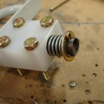
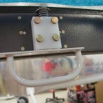
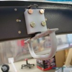
The major victory for today was the installation of the secondary canopy latch with spring modification.  I’ve mentioned a bit about this before; today I headed to the hardware store to dig around and come up with some springs that would work.  A found a 5/8″ by 1 9/16″ compression spring that was a perfect slip fit on the 1/2″ shaft of the latch, and had a good strong spring force.  To accommodate the length of the spring (it needs to be long enough to allow the latch to pull down far enough to clear the canopy frame), I chose not to cut the UHMW block down to capture only 2 of the mounting bolts, but rather to counterbore the block for the spring.  Since the 1/2″ hole is already drilled, I used a Unibit to enlarge it to the 5/8″ step, followed by a 5/8″ forstner bit in the drill press to bore the hole to the required depth (I went almost 3/4″ here).  Cleaned up the hole so the shaft slid freely, installed the spring into the hole, and capped with washer and cotter pin.  Pretty slick, I think.  I bolted the latch to the canopy frame, with the latch block spaced out from the frame by placing an AN960 washer on each mounting bolt, between block and frame.  This provided just enough space that the washer and cotter pin have clearance from the frame.  I did find a smaller diameter piece that could be used in place of the washer (sold as a 1/2″ ID x 1/8″ spacer), but the head of the cotter pin still needed clearance.  It’s easy enough to change if needed, but I don’t forsee a need to replace it; the latch arm has plenty of reach to the aft side of the canopy frame, to engage the rear window bow.

Number two: installed a newly-purchased screw to complete the installation of the pitot-static manifolds.

Number three: riveted in the magnetometer mount, and mounted the EFIS 1 magnetometer.  Also slid the elevator pushrod into the tailcone.

And, finally cleaned up the shop, including the massive nest of short wire bits that had collected on the bench…

Hours: 2.5 | Posted in Canopy & Frame, Electrical, Plumbing | Comments Off

6th July 2011

Odd jobs

Trimmed the UHMW block for the top canopy latch, and drilled the holes which bolt it to the canopy frame.  Found a washer that fits the shaft of the latch, and drilled the shaft for a cotter pin, but discovered that the washer’s OD is too large to fit on it; it hits the canopy frame.  I’ll have to dig deeper in the bags, as I must have pulled the wrong washer.  I’m also planning to install the spring modification that others have done, which allows the latch to tuck up parallel to the canopy frame, eliminating the possibility of locking oneself out of the plane if the latch were to slip.

Installed plugs in the open ports of the pitot & static manifolds.  I installed these manifolds to allow for easy expansion in the future, to run lines to a second/third EFIS, autopilot, and whatever new gadget comes along that needs it.  I haven’t found the second long screw I bought to secure these, though…looking like a fresh one from Menard’s.

Installed the center bearing block for the rudder pedals.

Shaped the upper body of the Gretz pitot tube slightly as needed to fit into the pitot mast, put the nutplates on the mast, and installed it to the wing.  Then, installed the pitot tube to the mast after trimming the pressure line and wires as needed, and wired/plumbed it.  I decided to try using a straight quick-connect union to join the 1/4″ copper line from the pitot tube to the nylon tubing which runs through the wing, since they’re supposed to be OK for all types of tubing.  If it doesn’t work, there’s plenty of room and remaining length on the tubes to do it a different way.  With the pitot installed, I rolled the wing cart over to the fuselage and plugged the left wing in, to verify operation of the heater.  Cooling it off with a cupful of ice water caused the heater to kick on, and the indicators indicated appropriately.  Check.

Drilled attachment holes in the rudder cable fairings, then match-drilled them to the fuselage.  I went with one hole in each corner for a total of three; if this proves not enough, it’ll be easy to add two more holes halfway along the sides.  I plan to attach these with blind rivets; easy, and easy enough to remove with a drill if needed later.  Primed the inside surface of the fairings and left to dry.

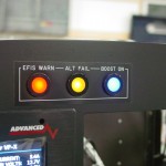
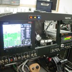
When testing the pitot heater, I had all three of the annunciator lights lit up on the panel, and grabbed a couple photos.  I really like how these LED indicators worked out, even though they were a bit pricey.  They may end up being too bright at night, but with the way they’re wired, it would be simple to add a bright/dim switch, or even a dimmer pot.  And, they should be dark in the normal condition, so it may be a non-issue.  (The camera makes them look brighter than they actually are, too; the hotspots in the photo aren’t apparent to the naked eye.)  I’m still very happy with the panel design & layout; putting that together was, as expected, one of the highlights of the project.

Hours: 3.1 | Posted in Accessories & Mods, Aft Fuselage, Canopy & Frame | Comments Off