5th
May
2010
Searching an escape from the treadmill that is life, both at home and at work, in these last few weeks of the season, I headed out to the shop for a bit of time on the project, and accomplished a few little tasks:
- Trimmed the holes in the aft end of the inboard baggage ribs, which I had neglected to do before riveting the tailcone on. A burr and sanding drum on the Dremel made quick work of this. Smoothed with a scotchbrite pad and spot-primed.
- Removed the aft deck and spacers, deburred all holes and edges. Deburred the drilled holes in the aft end of the longerons.
- Deburred all holes and edges of the baggage floors.
I have a small pile of parts ready to be primed, then the aft deck and baggage floors can be riveted in place, and construction can continue.
Looking ahead to the electrical wiring, I also removed the snap bushings from the tunnel at each bulkhead, and reamed out the slight lip on the inside diameter, to obtain the maximum diameter for wires. The 1/2″ step on a Unibit worked perfect for this. These bushings were then reinstalled. Curious, I tried to stuff one full of wire, and found I could pass (5) pieces of RG-400, with room for some smaller wires in the center and at the perimeter, or (3) pieces of RG-400 and (4) pieces of shielded 14-4, again with some room left over for smaller wires. What does this mean? Not much right now, but as I work through my wirelist, it should help with planning.
Hours: 1.6 | Posted in Upper Fuse & Skins |
25th
April
2010
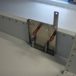
Thanks to the thread archive over at RivetBangers, I was able to figure out the appropriate location for the pitch servo bracket, as no dimension is given on the drawing provided by TruTrak. (The forward edge of the bracket is placed 2.8″ behind the centerline of the bellcrank pivot hole, if you’re looking for the info…this centers the bracket nicely on 4 existing rivet locations.). With that info in hand, I drilled out the four necessary rivets on the bellcrank rib, then drilled the bracket to the rib. I did the four top rivets, added three on the bottom, and then four equally-spaced rivets joining the bottom flange to the skin. To keep proper edge distance on the fore/aft edges of the flange, the rivets are not exactly aligned with those of the bellcrank rib, but this is on the center of the bottom of the plane, you’d have to crawl underneath and look up to see it–if anyone is putting in the effort to look that close to see if the rivets are misaligned, then I guess they deserve to find the mismatch!
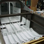
With the bracket drilled, I removed it and deburred all the holes, then dimpled the bottom skin with the pop-rivet dimple dies. I followed this up by looking at the install of the baggage wall; it looks like the baggage floor is supposed to go in first, so I pulled the bits that need priming out, to be dealt with later, and pulled the baggage floors out for deburring.
Of course, before the bag floors can go in, I need to run wire to the tailcone, or decide to run conduit under the baggage area. I’d also like to get a tech counselor out to have a look at the structure before I start closing things up; coordinating that with my crazy schedule through mid-May ought to prove interesting.
Spent some time with the shop vac, sucking up all the FOD that has accumulated in the fuselage from drilling and deburring. Finally, I got around to installing and torquing the 4 bolts that hold the seat ribs to the center section bulkhead, on the ribs that I had to reverse earlier.
Hours: 2.4 | Posted in Upper Fuse & Skins |
24th
April
2010
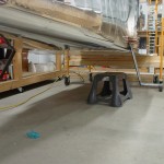
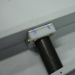
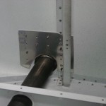
Finished the step install today: fit and drilled the right step to the fuselage, then drilled the plastic block to the rib and to the step tube. I also fabricated a spacer for the plastic block on the left tube that ended up slightly short, then drilled it in place, and drilled the block to the step. Finally, I fabricated some doublers for the side skins on both sides, to add some stiffness and take care of my too-large hole on the right side (though it turned out that there were no edge-distance problems, and it probably would have been fine without the doublers.) I essentially copied the step doublers that Scott Card installed…it just seems like a good idea to have a doubler there, since the skin is bearing the entire weight of the person on the step, and the step is also acting as a lever.
Steps are complete with the exception of one thing…due to the spacer on the left block, the called-out bolts are too short, and will need to be replaced with AN3-13A’s (of which I have no spares…will need to order some).
Hours: 3.6 | Posted in Upper Fuse & Skins |
21st
April
2010
Match-drilled both of the top skins to the structure, except for the longerons — since the underlying holes have already been drilled & dimpled, I’ll just run a reamer through all those holes in the top skins after they come off. Also match-drilled the 710 bulkhead to the aft deck.
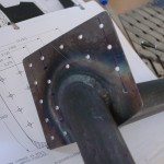
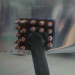
Browse the manual, what’s next? Steps…I’ve read this is tricky and I can see how it could be. The first step was to trim the end of the step tube, which was too long, and hit the baggage rib before the flange seated on the skin. The flange was about 1/4″ away from sitting flat, so I trimmed 1/4″ off the end, and somehow ended up 1/8″ short. Sigh. I’ve heard that there is some variation in these things–some too short, some too long, so I’m not going to worry about it, and may fabricate a spacer to bring the plastic block out the extra 1/8″.
Patience is certainly required, as there is much repetition of the bend-fit-remove cycle, trying to get the step flange to mate nicely with the side skins. After several tries, including some filing and a trip to the grinding wheel, I finally got a decent fit. Once fit, I pulled the step off and laid out two holes in diagonal corners, drilled, then back-drilled to the fuselage and clecoed in place. Marked the centerline of the rib that one row of rivets picks up, and removed again to lay out the rest of the hole pattern. I used only 4 rivets in the rib row, instead of 5, as at least one of the 5 would have been drilled through half of an existing skin rivet. With four, I was able to split the distance between the five skin rivets under the flange and have good edges distance on everything.
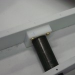
Several more fit-remove cycles were involved in fitting the plastic block that fixes the inner end of the tube to the rib, since my angle drill is too fat to fit in there nicely with the step tube there. I marked the hole with a #11 bit, then removed and drilled, before putting it back in place. For now, I bolted it to the rib, but did not drill the hole through the step tube, in anticipation of a spacer being fitted behind the block later.
Hours: 3.2 | Posted in Upper Fuse & Skins |
18th
April
2010
Pulled out the J-stiffeners that were made for the upper fuselage back when the rest of the stiffeners were cut; set them in place and taped their forward edges to the baggage bulkhead. These run three bulkheads back, and need to be drilled in assembly using the holes in the top skins. So, the aft top skin was clecoed in place first, to the bulkheads and longerons (after adjusting the angles of the bulkhead flanges to account for the taper of the fuselage). Once that skin was in place, the gussets connecting the 707 bulkhead to the longerons were clamped for later drilling (once the aft skins are removed, allowing access).
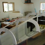
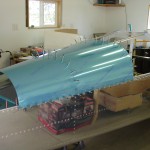
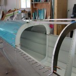
Next, the structure under the forward top skin is set in place: a gusset (which the manual calls F-688 and indicates needs to be cut & drilled, but in reality is F-788, complete and prepunched), and a rib. The forward end of the rib is clecoed to the baggage bulkhead, and the aft end affixed to the 707 by way of a cleat which is fabricated from a short length of angle. Before the cleat can be drilled in assembly, the skin must be set in place, so that happened next: skin in place and the J-stiffeners drilled from it. After the stiffeners are drilled, the skin is opened up along one side to give access for drilling the cleat to the bulkhead and the rib. After drilling and clecoing in place, the skin flap is clecoed back down. With both skins in place, the aft bulkhead that closes out the top of the fuselage is set in place, and the bottom-most holes drilled using the skin as a guide.
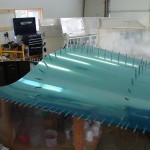
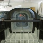
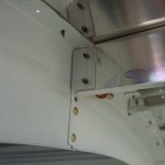
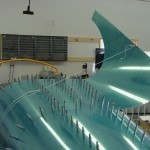

Once these skins are drilled, they will be pulled off for deburring, etc. I plan to get the static system and wiring into the aft fuselage before they are reattached permanently. 2 1/2 more pages in the manual until the first fitting of the wings–seems close, but it’s probably deceivingly far off.
Hours: 2.5 | Posted in Upper Fuse & Skins |
17th
April
2010
Completed drilling the aft deck spaces, fit and drilled the forward gussets at the firewall/upper longeron intersection. Drilled the harness anchors to the longerons, riveted the bellcrank support to the baggage bulkhead, and clecoed the small gussets that affix some of the tailcone bulkheads to the longerons. I’ll wait to clamp these in place until the aft skins are clecoed on.
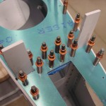
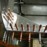
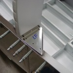
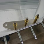
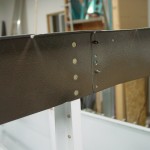
In spare time, doing mental and paper fiddling with the electrical system and antennas. I believe it will be easier to “design in” those things, rather than build the fuselage and add them afterwards.
Hours: 2.1 | Posted in Upper Fuse & Skins |
16th
April
2010
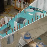
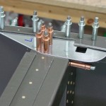
Now that the fuselage is upright, there is a myriad of small parts to be attached. Today, I finished drilling the aft deck to the longerons. I also fit the gussets behind the seats, which needed holes cut in them for the canopy latches to drop through. This also involved clecoing on the canopy decks, though I am sure they’ll end up coming off and on a couple more times. Finally, I fabricated the two spacers that fit under the aft deck, clamped them in place, and began drilling them in place.
Hours: 2.3 | Posted in Upper Fuse & Skins |
12th
April
2010
Picked up a digital level during the weekend out of town, so today I set out to level the fuselage and fit the aft deck. First task is leveling the fuselage, since it sits rather nose-up when placed on two equal-height sawhorses. After a couple of tries with various height objects, I got the front of the fuse set on a fixture of scaffolding and 2×4′s, and the tail supported with a sawhorse. One shim between a couple 2×4′s levelled the forward fuselage in the roll axis, and sliding the sawhorse fore/aft allowed it to be level in pitch. Twist is removed by adjusting the aft deck and clamping in place, which was surprisingly easy. (I was also interested to see that the 0.1-degree precision of a digital level is rather obvious on a bubble level, so perhaps the need for a digital level at this step is overstated, though it will surely come in handy when measuring control surface throws.)
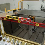
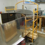
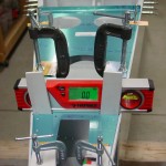
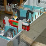
With the aft deck clamped securely, I took two more series of measurements before picking up the drill. I also left the level in place on the aft deck so I could check it between holes, in order to avoid any twist creeping in. I drilled every other hole before it was time to head in for dinner. The fuselage structure is now rigidly fixed in place.
My package of LED lighting strips also arrived today, direct from Hong Kong (SMD 3528 style from ledlightsworld.com, with the “IP65 waterproof-surface” rating). I’ve been using these for a project at work, and think they should serve nicely for interior lighting…I ordered blue for the panel, and warm white for general cabin/baggage lighting. I already have some PWM dimmers that I picked up some time back from another builder. I’ll have to play around and determine the best place to put them for cabin lighting, and the switchology.
Hours: 2.2 | Posted in Upper Fuse & Skins |
3rd
April
2010
This was the big day. Allison was back in the shop, and we started the fun by re-setting the outboard floor stiffeners from yesterday, then completed the inboard stiffeners. Riveted the aft row of rivets at the firewall (the forward row doesn’t get installed until cowling work). There’s a few tricky ones in there: the outboard few where the firewall weldment is very nearby, and the couple which are almost under the inboard angle brackets where the engine mount bolts on. With a few different bucking bars (including a big crowbar), we made it work.
While Allison took a break, I squeezed the longeron rivets that do not attach any top skins, leaving a patten of holes open on the left side for the clips that will retain the static air tubing. Next, I climbed under the fuselage and riveted the aft baggage-rib-to-bulkhead rivets.
After that was done, it was on to the tailcone join, which went quite quickly, just a couple rows of rivets, and up the side of the conical bend area.
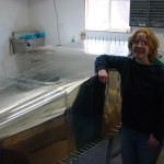
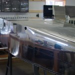
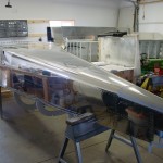
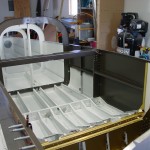
With all the riveting done, there was nothing left to do but take the plane through its first (and only) aileron roll… (can you do an aileron roll with no ailerons?) The canoe is flipped! Total build time to this point: 745.1 hours. Now the real fun begins!
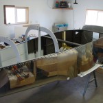
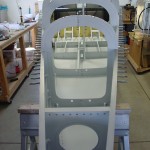
Hours: 2.4 | Posted in Center Fuselage |
2nd
April
2010
Two steps forward, .8 steps back… Allison came out tonight and helped with riveting — we did both fore & aft rows at the center section bulkhead, and the outboard floor stiffeners. About 5 minutes after we finished the floor stiffeners, I came to the realization (through a convoluted thought process) that the left and right outboard floor stiffeners had been transposed when clecoed in. (I must have mismarked them after etching and priming.) Essentially, this meant that the vertical leg of the angle was toward the outside of the fuselage, instead of the centerline. Looking ahead in the plans, I could see no problems this would cause, except for two things: first, the panels which hide the fuel & brake line runs would need to be altered, to move the notch for the vertical leg of the stiffener angles outboard about 1″; and second, any carpet underlayment foam would have to be cut to non-standard dimensions…not a big deal, but something to remember when ordering interior stuff, since the foam often comes with the carpets.
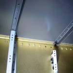
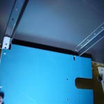
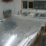
After some internal debate, I decided that I would just drill the things out, swap them, and be done with it. 50 rivets to drill out, all of which went fine without any problems. We’ll re-set these in tomorrow’s batch.
Hours: 2.1 | Posted in Forward Fuselage |


