30th May 2009

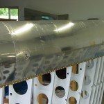
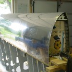
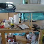
Wing skin riveting

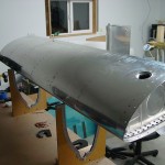
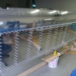
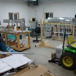
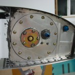
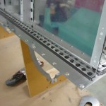
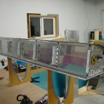
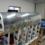
Stole Allison away from her work for a couple relatively short riveting sessions.  We set half of the skin-rib rivets on the left wing; with the swivel set on the rivet gun, she’s shooting like a pro.  Pulled the clecoes from the ribs, now ready to fill in the other half of the rivets, and the spar lines.  At least part of the rear spar should be squeezable.

Hours: 1.2 | Posted in Skin Panels | Comments Off

29th May 2009

Left wing ready to rivet

After assembling the left tank to the spar, I prepped & primed the left wing skins and J-stiffeners.  The primer goes on nicely and dries quickly in the warmer temperatures and light wind, making the priming less of a chore…but standing in the sun next to the bare aluminum skins is like a solar cooker!

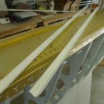
Once the primer had a chance to cure, I assembled the skins to the skeleton, again checking and re-checking the plumb bobs for twist.  The wing is pretty much dead on…less than 1/32″ difference from inboard to outboard end.  Clecoed every other hole…ready to rivet!

Hours: 2.8 | Posted in Skin Panels | Comments Off

29th May 2009

Left fuel tank installed

An afternoon of progress!  Began by taking the left tank out of the leak test setup and stashing those pieces for the right tank test.  I primed the tank’s top & bottom inside rear skins–where it contacts the spar–as well as the outboard end where it overlaps the splice strip.  I don’t know if this is really necessary or not, but since it’s in contact with other pieces, and I was setting up to prime today anyway, I figured it wouldn’t hurt anything.

After the primer had set, dropped the tank onto the spar and bolted in place, which went easily enough.  Followed up by installing the tank-to-spar screws, and only messed up the heads on 8 or so…sigh.  I think I need to find some better screwdriver bits.  They’re not too bad, but they’re a bit screwed up in the forward direction.  Throughout the process of attaching the tank, I was measuring and re-measuring the plumb lines to check for wing twist, but it stayed right on the whole time.

Some folks have trouble with the fit between the leading edge and the fuel tank, but mine is close enough that I don’t think it’s worth fretting over; it’s out by a half-skin-thickness in a couple places, but not bothersome.  I think this may be caused in part by the flat nutplates riveted to the curved splice strip, pushing it out of the necessary curve profile.

Later, I went back and did a final torque of the tank-spar bolts, and marked each one with torque-seal.

Hours: 2.8 | Posted in Fuel Tanks | Comments Off

28th May 2009

Leak check passed!

I’ve spent several days of on-and-off fiddling with the leak test of the left fuel tank, but am finally ready to declare victory.  It’s been holding pressure for almost 24 hours now, and passed the soapy-water test without any bubbles.  The fuel cap was the fly in this ointment–I had a bear of a time getting a leak-free seal.  The key, I think, is to use only as much tape as is required.  I was over-zealous with the tape for the first few go-rounds, which just created more joints where the air could leak out.  I tried the rubber glove trick…nope.  Tried chapstick (not having any Fuel Lube/EZ Turn) on the o-ring…nope.  (I have the “deluxe locking caps.”)  Finally, two very carefully-placed strips of packing tape seem to have done the job.

Pressure test was conducted using a homemade U-tube manometer built of small tubing, duct taped to one of the workbench legs.  The tubing is fit onto a stub of aluminum tubing and attached to the vent line fitting.  The tank drain was capped with the schrader valve from Van’s leak-test kit, however, I didn’t use that as the inflater, since I don’t have a bicycle hand pump (didn’t want to blow the tank by trying to use the compressor, either).  A piece of flared 3/8″ tubing was attached to the fuel suction fitting, and a short length of larger vinyl tube fit to the end.  Blow into the tube until the desired pressure is observed, fold the tube over, and clamp with a small vise-grips.  Perfect.  (The vinyl tubing didn’t leak–it’s ID was small enough that I had to heat it in order to slip it on the aluminum tubes.  Had there been leaks, I have some hose clamps that would have fit both junctions.)

Hours: 3.0 | Posted in Fuel Tanks | Comments Off

17th May 2009

AOA wing install

With the leftover Proseal from the left tank, I decided to install the AOA wing components, since they need sealant between the fittings inside the wing and the skin of the leading edge, in which a #60 hole is drilled for the actual port.  The install is fairly straightforward, as AFS provides measurements for properly locating the upper & lower ports.  They are installed at the same chord location, but offset a few inches from each other spanwise.  On the 9 wing, they end up behind the cutout for the leading edge lights, but the AFS guys indicate that’s no problem.  In addition to the two ports, a small hole is drilled in the bottom skin so that a plunger can be inserted to actuate the quick-drain at the bottom of the upper port (allowing any water which may have entered via the upper port to be drained from the system).

Of course, nothing is ever as easy as it seems; the port fittings install with two countersunk screws, which can fit into a #30 dimple (though they’re not actually #30 screws, it seems).  Drilling them was easy (remove the brass barb from the lower port fitting, and use it as a guide to mark the hole locations).  However, having already installed the leading edge to the wing, dimpling those holes was proved interesting.  There is no way to get a squeezer in there, as the end rib is in the way, plus the ports are 4.75 and 7.5 inches inboard from the skin edge.  I experimented with various tools, assemblies of tools, and different ideas without success.  I finally decided to do what is done on the rear spar: dimple, then “ream out” the dimple.  I dimpled to #40 with the pop-rivet dimplers, then used a #30 countersink in a microstop cage, going one step at a time deeper until the screws sat just flush with the skin.  Having already dimpled the skin prevented the countersink from having to remove too much material.

It may not be the perfect way to install these, but they’re in, and it’s what I had available.  Word to the wise: figure out these locations when you have the assembly clecoed together for the first time, and dimple them with a C-frame type tool!  Either that, or buy the #30 pop-rivet dimplers that I now see are available.  I don’t know if these will be needed elsewhere on the plane, but I may toss in a set with my next order of something, just to have around in case.  It’s a solution in need of a problem just like the one I had tonight.

After all that, I even found time to tidy up the shop and put away the various tools that have been laying around.

Hours: 2.1 | Posted in Accessories & Mods | Comments Off

17th May 2009

Left tank done

Concert season is winding its way to a close, lawn is mowed and the garden is ready for planting; finally a chance to get back into the shop for some quality Proseal time.  Finished up the left tank today, with only one major moment of frustration…

Before sealing things up for good, I gave as much of the tank as I could see an look-over with light & inspection mirror, with a special eye toward the skin-baffle joint and the four outside corners that received the “blobs” of sealant.  Everything looks good, but that can mean nothing–the proof is in the leak test.  Ran two beads of sealant from a syringe around the access plate opening, and clecoed it in place without trouble, then replaces clecoes with screws one-by-one in a star pattern, like lug nuts or head bolts, also twirling each screw in Proseal, and dabbing a bit in the hole, so that I ended up with a bed of sealant squeezed out around each screw head.

When the access plate was sealed on, all the screws in place, I began to go back with the torque wrench to check their tightness…that’s when it happened.  The second screw I torqued snapped off.  My smallest extractor was too big, so out came the other 11 screws, and a vise-grip was the tool of choice to run the broken screw fragment out the back of the nutplate (plan B would have been to drill off and replace the nutplate, but that has a greater risk of contaminating the inside of the tank with aluminum shavings).  Cleaned up the sealant with acetone, and did it all over again.  I used the screws that had been set aside for the second tank, as I didn’t know which of the 11 screws was the first one I torqued–I didn’t want to have another screw snap off, if I’d streched the first one.  I’ll pick up some replacement screws for the second tank; maybe even the hex-head cap screws some folks like to use.

I’ve heard of people over-torquing these AN fasteners many times, which is why I bought an in-lb wrench to use…I guess 20-25 in-lb is still too close to the bottom of it’s adjustment range to be accurate.  On the second try, I didn’t use the wrench, electing to use instead the ancient “gudentite” torque system.  (I did use the wrench on a bolt clamped in the vise, to get a feel for the required amount of torque…I’m confident I’m acceptably tight.  If these were structural fasteners, I’d try to find a decent torque screwdriver, but they didn’t have any at the stores I visited when looking for the in-lb wrench.)

With the access plate fun out of the way, I encapsulated the heads of all the rib-baffle and skin-baffle rivets.  After a few days to cure, this tank will be ready for pressure test.

Hours: 2.6 | Posted in Fuel Tanks, Wings | Comments Off

2nd May 2009

Left tank baffle

Finished up some details on both tanks: sealed the interior vent line conections, put the screws in the fuel senders and sealed them, sealed over the rivet heads for the anti-rotation bracket.  Gave a final look to the tank interiors, and wiped down the baffles with solvent to remove dust.
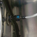
Lots of Proseal…installed the rear baffle on the left tank.  I erred on the side of “too much,” since it seems this is one of the more common places for leaks to occur.  Mixed up a plate of sealant, and another batch in a ziploc bag, which had the corner snipped off for use like a cake-decorating bag.  That worked quite well to lay the beads inside the tank, the blobs in the corners, as well as beads on the rear flange of each rib.  I also laid a light bead along the top & bottom surface of the baffle, and spread it thin with a popsicle stick.

Having masked off the spar-mating surface with blue tape, I slid the baffle into the tank and clecoed to the ribs, then every other hole to the skin.  Buttered up the back of each Z-bracket and clecoed in place, then went bank with the blind rivets, first twirling them in yet more sealant.  The ground-down puller worked fine, and none of the stems broke off high.  The end ribs are done with solid rivets, since the tails are on the outside of the tank.

Next, squeezed rivets in each open hole, from the center out to each end, then went back and pulled the clecoes and riveted the rest of the holes.  This requires a regular yoke with a deeper throat (my regular yoke isn’t deep enough, so I used the longeron yoke, along with the no-hole yoke where the Z-brackets interfered with access.

Finally, cleaned up the excess sealant from the outside of the tank, smoothed the fillets on the outside, and pulled the tape.  I set the tank on the floor with its aft side down, in hopes that gravity will help the still gooey sealant find its place in the baffle-skin joint.  I’ll need to go back and dab sealant on the heads of the rivets, then let everything cure for awhile before setting up a leak test with fingers crossed.
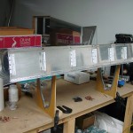
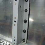
Earlier in the day, also managed to get the bottom spar dimples primed.  More primer on order, as I don’t have enough in the can to do the wing skins.
Hours: 5.9 | Posted in Fuel Tanks | 1 Comment

30th April 2009

Fuel tank details

My Rolo-Flare tool arrived in today’s mail, so spent some time fiddling with it on a piece of scrap tube, then did the flares on the fuel tank vent lines and attached them to the bulkhead fittings.  Also drove the two rivets in each tank that were a pain before, where the inboard attach bracket is too tall for the straight rivet set (much easier to set now that the sealant is cured, and not lubricating the set; was able to use the single and double-offset sets to finish them up).  All that remains on the tanks is to encapsulate those inboard end rivets, Proseal the vent line fittings, and attach the baffles & Z-brackets.

Hours: 0.6 | Posted in Fuel Tanks | Comments Off

30th April 2009

Right LE attach, skin prep

Finished attaching the right LE assembly to the spar by squeezing the top & bottom rivets in place.  Done.  Pulled out the left top wing skins and deburred, edge-finished, and dimpled them; ready for primer, but too windy to prime today.  Made it through spot-priming of half the rear spar dimple/countersinks before dinner.

Hours: 6.2 | Posted in Skin Panels | Comments Off

25th April 2009

Leading edge two

Jacked up the right wing, measured and tweaked the fixture, then clecoed the leading edge assembly in place.  More measureing and checking, then riveted the rib-spar rivets, as on the left wing.  All came out fine, only had to drill two.  Allison did a great job driving the rivets on the two-man rib (third inboard).

Hours: 1.7 | Posted in Skin Panels | Comments Off