30th January 2011

Tailcone closeout work

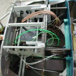
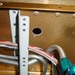
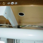
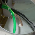
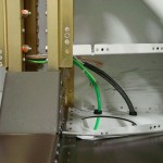
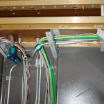
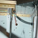
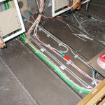
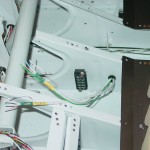
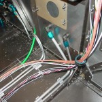
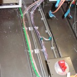
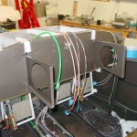
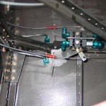
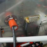
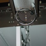
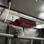
I’m trying to close out wiring and stuff aft of the center section, so that the wiring runs in the tunnel can be cleaned up and tied down, then work forward with the wiring.  To that end, I finished running all the wires I could aft of the center section, which today was the ELT remote (4-22 shielded) and the GPS signal run (3-22 shielded) which will feed both the ELT and the APRS tracker that I’ll mount in the same area.  That finishes the aft wiring, except for five wires: 4 audio cables (pilot & pax headset & mic runs), and the cable(s) to the magnetometer(s) — I’ll run wires for 2, since each screen with airdata needs it’s own magnetometer — all of which will be included in the harness kits from SteinAir, so I’m waiting to run those.

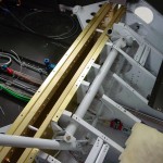
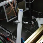
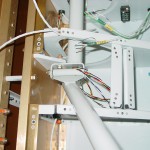
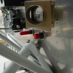
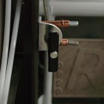
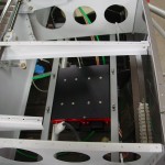
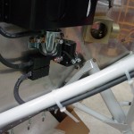
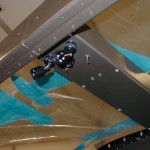
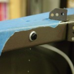
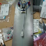
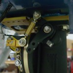
With most of the wiring aft of the firewall in place for the time being (until the harnesses are ready in a few weeks), I moved on to other aft-of-the-spar tasks — namely, the control system.  I removed, primed, and reinstalled the pushrod that connects the two sticks in the roll axis, and built the forward elevator pushrod, as well as bent and installed the tabs that bolt onto the control column to connect the roll trim springs.  I used a piece of light safety wire to thread the washers and rod ends into the sticks properly, but still need to torque those bolts.

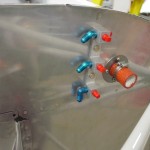
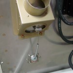
I finally got around to some housekeeping — vacuumed out the forward part of the cabin of metal shavings and debris.  I need to reclaim my shop vac from the office and vacuum out under the seat pans, as I’m sure there is schmutz down there as well.  Also, taped over the intake to the fuel servo to prevent the shop spiders from taking up residence in the induction system.

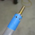
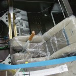
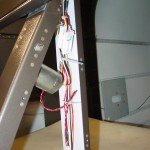
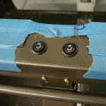
Another task for the evening was to cut the sticks down.  I measured both sides and decided to cut off enough to compensate for the length added by the stick grips (~ 2.5″), plus another half inch.  Some builders cut them way down, but I’m taking a wait-and-see approach to that, as it’s easy to cut them down farther later, but far more difficult to add some back on.  After I cut them down, I (of course) had to load in the left seat and panel blank, and test it out.  The length seemed pretty comf0rtable to me, and it does not appear that they will hit the panel (using a ruler to simulate the ~1.5″ I’ m adding to the bottom of the stock panel.

I’m working with a gent who posted on VAF about doing some panel cutting for the cost of materials and shipping, and I think we have the measurements worked out; I’ll be drop-shipping an oversize blank to him this week for cutting, so that’s coming together as well.

Hours: 5.5 | Posted in Center Fuselage, Electrical | Comments Off

29th January 2011

Still more airframe wiring

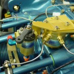
First item on today’s list was the intake studs on the engine sump.  The ones that were on the engine as shipped were too short for the fuel servo and spacer/mount bracket, so Aero Sport Power sent out a set of longer ones.  The shorter ones were removed last week, and I picked up some high-temperature threadlocker (Permatex 27200) to put on the new ones, as recommended in the Airflow Performance install manual.  A few drops on the far end of the stud, a pair of nuts, and they were on and looking good.  Test-mounted the bracket and servo to make sure the length was good (it was), and to look at routings for control cables and fuel lines.  I’ll hold off on all that until I have an exhaust system, so as to not create any interference.  Also need to work out the location of the fuel flow transducer, which will go in the feed line between the servo and the spider which sits atop the engine.

Trying to get the airframe wiring (wiring that runs to various parts of the plane — as opposed to the panel wiring, which would connect the boxes on the panel and generally contained within the “avionics bay”, or engine wiring, which would run to the forward side of the firewall) generally wrapped up.  I have just about run out of space in the bushings that run through the center section, and still more wires to run, so it was time to add another bushing.  Evaluating various cable paths, I decided to put it under the fuel valve, to the right side, 2/3 of the way up the spar web, which would allow the wiring to run without chafing on fuel lines or interfering with the control column, and kept a good distance away from the other bushing holes.  A pilot hole a long #30, then a unibit made quick work of the holes, and I was able to use a 1/4″ drive handle to turn the unibit inside the center section to deburr the backside well.  Primer, then snap bushings.  (Tip: the snap bushings have a “ridge” on the inside diameter of the flange side that can be removed with a unibit, giving you an extra 1/16″ diameter…I’ve done this to all the bushings in the center section, to gain as much space as I could.)

More wires to run…2 coax lines for GPS antennas behind the rear window, plus power and ground for the ELT and APRS.  Need to look and see what the specified wire is for the magnetometer runs, as well as the GPS feed to the ELT/APRS (which will share a single feed line).  Also finished up the last of the wing wiring with the OAT, pitot heat, and landing/taxi light wires.  I tied up the bundles that run from the tunnel out to the wing roots, and sleeved the wires that pass out of the fuselage.  These will get CPC connectors on both sides, and the sleeving will be maintained all the way into the connector backshell.  I also put the straight union connectors on the AOA lines — the tails from the wing will pass into the fuselage, where they’ll be joined under the seat pan.  May do the same with the pitot line, but for now it’s run out the side.

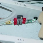
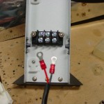
Terminated the nav/strobe wires at the terminal block under the seat; this looks like it ought to work out alright, though were I to do it over, I would have put the snap bushing for the aft wires farther away from the terminal block.

Hours: 7.5 | Posted in Electrical, Engine, Plumbing | Comments Off

24th January 2011

More electrical and plumbing

Not much to look at, so not many photos today.  Ran more wires and tubes, including the wires for the stick functions, and mounted a terminal block for the nav/strobe lights.  The power will feed to this block, then run to the wingtips and tail…this makes it so that only 1 cable needs to pass through the spar, rather than 3.

Hours: 4.2 | Posted in Electrical, Plumbing | Comments Off

23rd January 2011

Electrical and plumbing

Installed the bulkhead fittings on the firewall for the fuel feed and purge return lines — I think I will also install a doubler on the aft side of the firewall that picks up both fittings, as they’re a bit wobbly yet.  Bent and test-fit the fuel line from pump to firewall, and fabricated a purge return line to run from the firewall back to the tee under the fuel selector.  Installed the elbow fittings in the transducer manifold.  Mounted the 4-channel lighting dimmer, and ran more wires.

Hours: 6.1 | Posted in Electrical, Plumbing | Comments Off

22nd January 2011

Electrical work

Fit the parking brake cable (t-handle; each cable function will have a different visual and tactile design) and test-fit the brake valve end.  Need to get an adel clamp to fix the cable end in place.  Installed both heater boxes, one on the right edge of the firewall, and one in the usual center position.  Installed the cable eyeball for the right box.

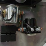
Fabricated and installed mounting brackets for the VP-X control unit.  Installed battery and ran heavy-gauge wire on the FWF side, and the main buss feed to the VP-X.  Finalized install of the contactors and main fuses (alt feed & main buss), preliminary install of the alternator wire (need more adel clamps).  Worked on layout of wiring runs and installation of adel clamps in the “avionics bay”, with an eye toward being able to service them from underneath the panel once the top skin is in place.

Also located and installed a bunch of tie-wrap bases in the forward tunnel with Goop (rather than the adhesive pads) to support two wire bundles, brake lines, and fuel lines.

Hours: 9.4 | Posted in Electrical | Comments Off

16th January 2011

Aft electrical

More electrical work today, though it doesn’t seem like much was accomplished for the time I spent.  After finishing the installation of the terminal block for the heated seats and hooking it up, I decided to remove it and use knife splices instead.  The terminal block was nearly as wide as the channel it was mounted in, and the bundle of wires running the rest of the way up the channel would have needed to pass over it.  I didn’t like the looks of it, as it seemed like an opportunity for wires to chafe and short to the relatively large power line feeding the seats.  I may redo it yet again with a Molex connector of some sort later…the Molexes I have now are only rated to 6 amps.  I think heatshrink over the knife splices will be sufficient, however, and removed easily enough if necessary.

Next, I struggled with fitting the wiring harness for the heated seats into the allotted space.  I dug out the nut-sert kit and put nuts on the left & right side of the tunnel to secure the relays; since these nuts have no self-locking feature, I used blue Loctite on the #8 screws.  Also installed a wiretie base to secure the large harness/connector that leads to the relay.  After monkeying with the switch harness for some time, I decided to remove the factory heatshrink, which made things far easier to deal with.  I think that since it’s sold for installation into cars, they cover all the wires with the heatshrink so they’ll be protected when people don’t secure them properly.  The rest of the wire bundles aren’t covered with heatshrink, though, and everything will be secured well.  Without the covering, the bundles are much more flexible and I was able to spool up the excess and secure it.  This could be shortened with appropriate connectors, as well, but I have nothing that’s rated for the current at the moment.  I also radiused the bottom corners of the aft flap channel to provide an opening for the leads to exit en route to the cushions.

Next up was installing the map light panel — which meant running a pair of wires to it — which meant installing wire bases along the path.  As long as I was stuffed into the baggage compartment with the appropriate tools, I also laid out and put wire bases on paths to the AHRS mounting area and over to the ELT mount.  With all the bases in place, I pulled in the wires to the map light and put a Molex on the end, then connected and installed the map light panel.  Stuck the wire ends under the battery bolts and flipped the switches, and they lit up.

Also spent an hour or so this afternoon adjusting the panel CAD, after I realized that I had the radio stack too far to the right.  The position doesn’t matter for anything that doesn’t penetrate the subpanel (since we can cut off the ribs aft of the subpanel and install them wherever they work), but since the radios need to go through the subpanel due to length, they cannot be positioned over the left or right ribs, as that’d interfere with the rib forward of the subpanel.  5/8″ to the left, problem solved.

Hours: 5.8 | Posted in Electrical | Comments Off

15th January 2011

Random electrical

After spending much of the day getting the CAD panel design wrapped up, I worked on a bunch of little things, mostly electrical, tonight.  I was stymied in a couple places by many of my tools and supplies being at the office, so some jumping around was unavoidable.

  • Assembled and installed protection diode on the starter contactor, then torqued nd marked the contactor mounting bolts…this means the contactor install is complete.
  • Placed the battery in the battery box.
  • Drilled holes for the auxiliary PTT switches (both left and right; right is essential for when the copilot stick is out, and the left will be handy to transmit without disturbing the stick when on autopilot).
  • Installed a Molex connector on the map light panel leads to allow for easy future removal for service.
  • Installed a Molex connector on the flap motor leads; same idea, especially knowing that this in even more likely to need to be serviced in the future than the LED map lights.
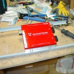
  • Played around with some ideas for mounting the Vertical Power control unit; I could use the upper firewall angle as one mount point for a pretty clean install, but the mounting screws would be nearly impossible to get to after the top skin was on.  I think I will run a pair of angles left-right across the bottom of the forward ribs, and mount the box to those.  That’ll also provide for a good way to run wires left-right across the cockpit, and to strain-relief the harnesses to the control unit.  The main buss wire looks like it will have a manageable path, as well.
  • Drilled and installed the heated seat switches in the crosspiece aft of the seats.  This position will require loosening a harness to reach in flight, but it solves the problem of needing to pass a bunch of wires through the spar.  I saw this in a local builder’s plane recently, and he mentioned that downside, but said he would probably do it the same way again.  I’ll only need two wires through the spar this way (both seats are sharing a power pin on the VP-X).
  • Located and installed a terminal block on the vertical member under the crosspiece for the heated seat power.  Removed the plastic connector from the end of the harnesses and installed ring terminals for connection to the terminal block.
  • Looked at where to mount the heated seat relays; I plan to put them in the tunnel under the baggage compartment, mounted to the outboard sides.  I temporarily installed the elevator pushrod to ensure there won’t be any interference.
  • Modified the connectors on the seat heat harnesses by removing the mounting tabs, which aren’t used in this configuration; this makes them a bit smaller, to better fit in the tight spaces they need to run in.  Disc sander make quick work of this.

Hours: 3.6 | Posted in Electrical | Comments Off

14th January 2011

Panel planning

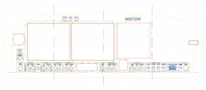
Having my phase 1 panel components on order from SteinAir, I thought it was time to get serious about designing the panel layout.  Hence, I invested about ten hours over the course of an evening and the next day drawing my panel in TurboCAD.  I have the software from work, and have used it for several things in the past, but it’s been several months so it took a bit to get back into the swing of things, especially as I know just enough of how to work it to get by.  (Tip if you’re looking for a place to start: learn all the things you can use Constructions for…)

My thanks and apologies must go to Mike Behnke here — I really like the way his panel turned out (and Bret Smith’s as well, which they collaborated on).  He graciously sent me his CAD file, which was a great starting point for layout and measurements.  I used the DXF of the panel blank available from Vans’ website, since I have a tip-up, and copied some of Mike’s pieces, then drew all the stuff I wanted, often based off of stuff in his file or that I had seen elsewhere.

One of the pieces that I’m including is backlit switch labels, which include a series of cutouts behind certain legends on the panel which will be illuminated with an LED light strip.  The engraved labels will lay over the cutouts, so the design is integrated using multiple CAD layers, so everything can be correctly aligned, then extracted and sent to the respective vendors for machining.

I really enjoy the process of designing these systems, and drawing up the layouts as well.  While the overall layout is inspired by others, I’ve done a bunch of designing, either on paper or in my head, on alot of the electrical systems that will be in the plane.  It’s satisfying to sit down with the electronics catalog and datasheets and think through different ways things could work, and come up with switchology or buttons or indicators that work the way I do, and finding the right parts to make them work and look a certain way.  I enjoyed the metalworking part of the project too, but I’m especially partial to the systems stuff.

Once I had the panel design pretty close, I printed it out on tiled sheets of paper and put them together, then sat for a bit and looked it over in actual size.  Put the dimmer knobs over the drawing to make sure they were spaced far enough apart that they could be grasped, and so on.  Made some adjustments and tweaks, and set it aside…I’m sure another round of looking later in the weekend will reveal a few more things that come to mind.  (I also need to do some measuring to ensure there won’t be any interference between the EFIS and the canopy stiffeners.)

I’ve planned for dual AF-4500′s, along with the Garmin stack: 240, 430W, SL40, 327.  The flat-pack autopilot head mount is integrated into the row of controls at the bottom of the panel, along with the CO detector/pulse oximeter.  Flap switch is above the throttle lever for ease of operation.  There is enough space on the right side of the panel for an AF-3400 or other EFIS screen, if future expansion is desired, and I’ve put (at least for now) a 2.25″ instrument hole on the left as well, which could be used for some sort of backup instrument (such as the Trutrak ADI) down the road.  The bottom flange has been dropped 1.25″ from the stock panel to give additional height for all the gizmos.

Once this is finalized, it’ll go off to someone to be cut by waterjet or CNC, and the labels to be engraved.  When the avionics arrive, hopefully I’ll be ready!

Hours: 10 | Posted in Electrical | Comments Off

9th January 2011

Engine hanging

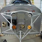
Before the engine could go on, there were a couple remaining items to take care of.  First, the nose gear had to be installed, and the wheel bearings greased.  I’ve packed bearings before, but these were difficult because they have a rubber seal on one side of the bearing, so the usual “pack it in ’till it comes out the other side” didn’t work out.  I packed it in as well as I could; the glob in my hand kept getting smaller, so it must have gone somewhere, but I’m not sure it was done perfectly, so I may revisit this wheel when I repack the mains prior to flight.  I also looked at the preload adjustment on the Matco axle; you’re supposed to tighten the preload ring until the bearings remain stationary to the axle while the wheel rotates.  I was able to get them to not rotate, but the wheel is very stiff…need to do more reading on this.

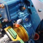
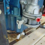
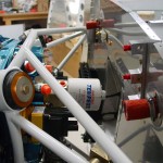
Item number two was to move the oil pressure fitting on the engine from the side port to the rear port.  I removed the fitting and the plug, and swapped them, installing the plug with EZ turn to the specified torque (which involved tracking down a copy of the Lycoming torque specs in Lycoming  publication SSP-1776).  The pressure fitting is just finger tight for the moment, until I determine if it ought to be a straight fitting instead (and if so, make one with a restrictor).  While I was monkeying with the engine, I also pre-installed the 90* fitting with the pressure tap on the fuel pump outlet.

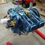
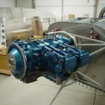
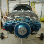
With all that done, I took another look through my pre-engine hang list, and decided it was time.  I followed the “Illustrated Guide to Engine Hanging” and the procedure was pretty straightforward.  The trickiest part was the upper left bolt, as the nut is close enough to the pushrod tube that a box-end wrench gets trapped by the bolt when fully tightened, and the hole in the engine case is such that a box-end can’t get on the nut well.  I ground down a cheap box-end wrench so it was thinner along one edge, which let me remove it after the bolt was torqued.  Getting the cotter pins in was fun as well, and required some attention during the torquing process to see that the holes ended up in an accessible orientation.  In the end, no problems with the hang, and it’s looking good.

Once the engine was on, I couldn’t resist pulling out the fuel servo and test-fitting it. The AFP kit includes a nice anodized bracket/transition piece which fits between the servo and the sump, however, it is rather thick, and with it in place, the studs on the sump aren’t long enough to allow for the washer, lock washer, and nut.  In fact, they don’t even protrude through a single washer and nut.  Without the spacer in place, the throttle linkage hits the bottom of the sump, so clearly it needs to be there, and it also provides a mounting location for the control cable brackets.  I’ll have to look into the length issue.  Also need to look into how the airbox is intended to fit onto the servo; the parts are all there, but it’s not immediately obvious which way they’re all intended to go.  Lastly, I moved the throttle, mixture, and purge valve levers to the approximate locations they’ll need to be for the control cable attachments.

(Engine hang at ~1110 hours.)

Hours: 4.9 | Posted in Engine, Gear & Fairings | Comments Off

8th January 2011

Firewall sealing

Spent the morning at the Minnesota Wing meeting, talking and looking at a local RV-7 that was recently finished, which provided some good inspiration to move ahead on the FWF stuff; also had the change to talk to folks about some open questions: mufflers and heater boxes, seat heat switch location and wire routing, transition training, and so on.  Notes to self: the Torx screws on tips and hex-heads for interior panels look nice; heated seat wiring can be run out underneath the flap motor housing, and the cushion cables are long enough to reach; relays can go in the flap housing with switches on the crossbar (though they are hard to reach in flight, it cuts down on wiring run through the center section).

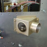
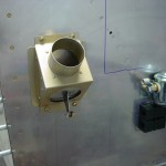
Back in the shop this afternoon, my goal was to get most of the firewall components installed and ready to hang the engine tomorrow.  Number one on the list was the heater boxes.  I chose to mount one in the center, feeding into the stock diffuser box; the second one is placed on the passenger side, far outboard.  I oriented that one with the outlet (which dumps the heated air when the valve is closed) pointing down, thinking that it would provide better airflow to the lower cowl exit.  This meant that the box had to be up the firewall some amount to allow room for the control cable to exit below it, so it ended up next to the battery.  Hopefully I don’t regret this, but I’ve been pondering it for several weeks and it was time to make a decision and get on with it.  I think in this location, it would be easy to add a flange on the cabin side if desired later, to direct the air from that vent to an eyeball or glareshield vent.  Everyone I talked to who has the muffler exhaust, or has flown a plane with it, is pleased with it and says that there is more than enough heat output, which will be a good thing.

I used a 2″ hole saw (buying the kit of quality hole saws was a good move, as I’ve had zero difficulty cutting the stainless) with the drill motor slowed down (regulator set ~35psi) to make the holes, and used the doubler for a template to drill the mounting holes.  I decided to use #8 screws rather than the #6 called for in the plans, mostly because I had truss-head #8 screws, and only countersunk #6 screws.  And, rather than using nuts on the backside, I put nutplates on the doubler to allow for easier one-man installation and future service.  These are the triangular heat boxes from Robbins Wings, which have a stainless steel hinge and flapper, with an aluminum box.  The theory being that if there was a fire, the box might melt away, but the flapper, being stainless, would remain to cover the 2″ hole in the firewall.  This is a variation on the all-stainless box, and seems good to me.  They include the doublers, and are set up for control cables on the engine side.
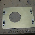
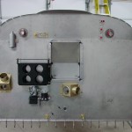
With the heat boxes in place, the next order of business was to install the firewall recess.  Besides removing the top skin, this meant mixing up the firewall sealant, Flamemaster CS 1900.  It is a two-part concoction, similar to Proseal, but part A is a very stiff paste and part B a thin liquid; it is difficult to mix, and remains very thick after mixing.  The data sheet indicated that it could be thinned for application, including brushing, by use of ketone solvents.  A little research told me that acetone is a basic ketone solvent (which saved me a trip to the store for MEK), and it took a lot of acetone to get it to a workable consistency.  Put it in a freezer bag for application, same as I did with the Proseal on the fuel tanks.  After wiping all the parts down with solvent as instructed, I ran a bead between the recess and the firewall and clecoed it in place.  I let that begin to set up while I sealed and installed both wiring pass-thrus, and sealed around the brake reservoir penetration.  Then I went back and riveted the recess in place, and sealed around the edges and in the seams and corners, filling the holes at the corners with a blob of sealant.  Cleaned up the mess and called it good.  Once the recess was in and the sealant had tacked, I bolted and torqued the battery box and heater boxes.  No pictures of the sealing process, because it’s hard to use the camera when your hands are covered in black goop.  The copius acetone thinning didn’t seem to affect it’s ability to cure, and it skins over fairly rapidly after dispensing.

Once the sealing was complete and cleaned up, I installed and clamped the outer firesleeve on the wiring passthrus, as it needs to be in place before the wires are run, and I didn’t want to forget it later and have to take all the wires out to install it.  (Like flaring tube without a B-nut, or soldering a connector without the backshell — not that I’ve ever done either of those…)

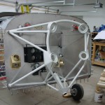
Engine mount is next…had to fit and remove a couple times to work on the nose gear bolt clearance, and I ended up putting a little “dent” in the firewall behind the gear leg to shift it aft and provide clearance for the bolt & nut.  I’ve read that this is not uncommon.  I also had to file a bit more off of the lower fuel pump nutplate to clear the lower mount tube, and I filled both nutplates with firewall sealant, since I’m not using them (this pump location is used only for carbureted engines; I wasn’t sure whether I would have carb or FI when I built the firewall, so I put the doubler & nutplates in).  As of now, the engine mount is bolted up, but not yet torqued, as I expect to need to remove it (along with the engine) one more time to drill and install all the cable and plumbing penetrations, once I figure out where they need to go.
Hours: 4.9 | Posted in Engine, Forward Fuselage | Comments Off