2nd February 2012

Venting

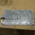
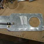
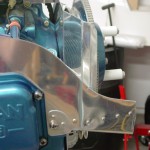
Drilled and installed the fairing nutplates on the HS.

Countersunk and re-primed the top cowl camloc strips (oops).

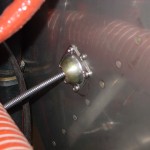
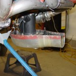
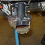
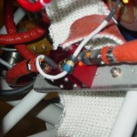
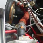
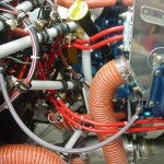
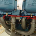
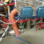
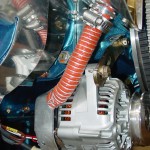
Cut and attached the blast tube to the alternator with a double-wrap of safety wire.  I’m all ears if someone has a better way of doing this, but it’s reported to have worked.  Also rumors that the alternator doesn’t need it, but cooler is always better for electronics.

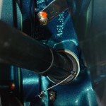
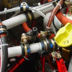
Tightened and re-saftied the dipstick tube, as it was weeping just a bit at the gasket, since the engine is full of oil now.

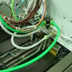
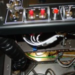
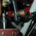
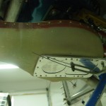
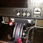
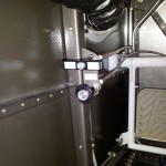
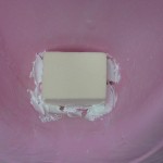
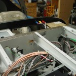
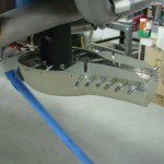
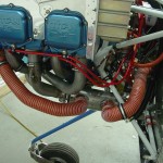
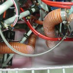
Installed the alternate static toggle low on the subpanel behind EFIS 1.  I bought a toggle switch guard to put over it, since the actuating force to open the switch (thereby venting the static system to the cabin) is quite low.  The guard needs a good strong push to open & latch, and it holds the valve firmly closed in the down position.  I sat in the seat and the switch is out of sight, though easy to reach under the panel.  It still needs a placard, though, because my labeller was too cold to print labels.  (It looks like the wire bundle is very much in the way, but it’s just a result of the camera location.)

Checked to be sure I’d run the remote output port from the transponder to the ADS-B connector (I had), as the need for that connection came up on a recent VAF thread again.

Wasted the rest of the night sitting in the seat playing with the avionics.

Hours: 2.4 | Posted in Engine, Plumbing, Wing & Tail Joins | Comments Off

26th January 2012

Pickle me

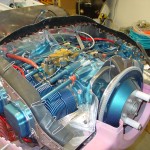
It’s been a but more than a year since my engine was built, and the protections applied at the build shop were said to be good for 12 months.  I’ve been careful not to turn the engine, and have kept it’s openings mostly plugged, but I asked the kind folks who built the engine up at Aero Sport Power what measures I should take to prolong the preservation, given that it will likely be several more months before the fires are lit.  Having procured the necessary items, I carried out their recommendation tonight:

  • Pour 3 gallons of oil into the crankcase.  They said this could be automotive oil, as it’s only there to cover and protect, not lubricate for flight.  I put in conventional (non synthetic) Valvoline.
  • Cap off the breather and exhaust stacks.  I had a plug that fit into the breather hose, and I wrapped the stacks in plastic & tape, since I don’t have any plugs that large.
  • Cap off the intake; this is already done, before I started doing any fiberglass work on the FAB & intake scoop.
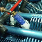
  • Insert dehydrator plugs and keep them dry.  I looked around and found some that the crystals can be taken out of and dried.  Make sure to ask that, as there are several places selling 14mm ones that are sealed, alongside the regular reusable 18mm versions.

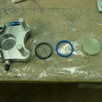
I’ve been doing final reading on brake fluid & seals, and I decided to change out the caliper O-rings, since the stock Buna-N ones will deform in the 250* range.  There have been cases of brake fires on RV’s and similar aircraft before, so many guys are replacing the 5606 fluid (flash point in the 200′s) with the more modern 83282 (flash point in the mid 400′s).  Synthetic ATF is another option, which has specs similar to that of the 83282.  It’s also become common to change out the O-rings with Viton, which is rated to 400*. The downside to Viton is it’s poor low-temperature performance (-15*).  Since I do plan/hope to fly in the winter, I found some flourosilicone O-rings at McMaster, which have the same high-temp rating as Viton, but are also rated to -75.  (They’re listed under “military specification o-rings,” p/n 8333T255)… a little pricey at $6.25 for a 2-pack, but that’s small potatoes.

The install couldn’t be easier: remove the caliper, pop out the piston, remove the old O-ring, clean up the piston & bore, lube the O-ring and insert it, then slide the piston back in place and re-assemble.  Done.

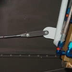
Finally, the mixture linkage has been bugging me for awhile; even with the higher hole I drilled in the quadrant lever, it wasn’t confidently hitting the stops on the fuel servo before hitting the end of the quadrant throw.  (Yes, I tried a bunch of different arm angles.)  To solve that, I pulled the mixture arm off and drilled another bolt hole a bit higher than the existing one, then reinstalled.  Works perfectly now, the stops are hit before the quadrant lever runs out of travel, and the throw matches that of the throttle lever.

Hours: 1.9 | Posted in Engine, Gear & Fairings | Comments Off

21st January 2012

Airbox assembly

Installed what should be the last firewall eyeball, for the alternate air control cable.

Fooled around with a piece of ceramic batting, to explore how it would work to fit it on the cabin side of the firewall.  I wish it were stiffer, the stuff I ordered is sort of floppy.  I think it would stay in place if cut to the right dimensions and backed with metal foil. I may do this yet, but still waffling.  Plenty of planes flying without it…  If I do decide to put it in, I want to do it before the top skin is riveted.

Attached the cable-end fitting to the alternate air slider assembly, then drilled the assembly to the airbox.  Made spacer strips for each side so the cotter pin wouldn’t rub on the fiberglass.  Riveted the slider to the airbox, with an RTV “gasket” to the hole in the bottom of the box.

Cut the filter holder clips and drilled them to the airbox top; deburred, countersunk, and installed with nutplates.  Riveted the airbox top to the glass bowl, again with a bead of RTV around the perimeter for an airtight seal.  Temp fit the whole airbox assembly to the fuel servo.

Hours: 4.5 | Posted in Engine | Comments Off

28th December 2011

Letting it breathe

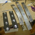
Spent most of today working on the FAB install, namely fabricating a sliding-door mechanism for the alternate air intake, which is a safety feature which will allow the pilot to keep the engine running in the event the regular air intake becomes clogged (filter icing, bird ingestion, etc).  I’ve made a copy of a design that was floated on VAF, which utilizes a stacked-plate configuration affixed to the bottom of the airbox, rather than the hinged circular door supplied in the kit.  This design solves the weak spot (hinge ear) in the supplied piece, and further reduces the possibility of hardware ingestion if something were to come loose inside the FAB.

Along with the sliding door mechanism, which I’ve test-fit, a control cable is required.  I didn’t make any provision so far for this cable in the cockpit, but I was able to re-make the bracket near the pilot’s left knee that I’d put in previously to hold the parking brake control.  Now, the parking brake and alternate air controls are there, one above the other.

I also made labels (at least temporary ones, since I’ll redo them in black tape later) for the various control cables:

  • Cabin Heat / Pull Open (x2)
  • Fuel Purge / Pull Open
  • Park Brake / Pull to Engage
  • Alt Air / Pull Open


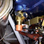
And, I removed the oil drain plug from the RH drain port, and installed the Fumoto quick-drain valve I picked up awhile back.  It doesn’t come with any provision for safety-wiring (being an industrial equipment piece, rather than aviation-specific), and I didn’t like the first attempt, which wrapped a loop of wire around the valve body; it seemed possible for the wire to shift and open the valve, clearly not a “safety” outcome.  I ended up drilling a hole through part of the flange, and safetying it to the boss provided on the engine sump.

Hours: 7.0 | Posted in Engine | Comments Off

27th December 2011

Somewhere, under all the dust

Happy Holidays — Christmas Eve is the anniversary date of the arrival of the empennage kit, so this marks the beginning of year 6 of the project.  I really hope to get this plane flying this year, though enough plans have been laid and lost that I won’t bank on it at this point.  The biggest remaining hurdles are all the fiberglass work, final assembly, and the “tax kit” (yes–thank you Minnesota–I will be required to pay over $6k in various taxes and fees before I’m allowed to fly it, and then a significant ongoing annual tax, as well…)

With Christmas as the associated family travel receding into the distance, the holiday schedule at work lined up to give us two 4-day weekends in a row.  I, like many others, decided to cash in a bit of stored-up PTO to have a 9-day mini-”vacation” from the office, before heading back to build out another recording studio in January, along with new student training and a bunch of deferred maintenance items.  And, I’m putting off the non-work work that I need to do a bit longer, in order to log a couple hours on the airplane project.

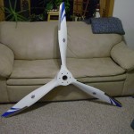
Today’s task was to find the thing under the pile of hay, dust, and remodeling debris that has accumulated in the shop since I last touched it over three months ago in September.  Several hours later, the shop was clean again, and most of the tools found and returned to their home.  A new storage stack was built out of cabinets removed from the kitchen, and more things stored away in the attic.  With the floor swept, I was able to move the plane out where I could walk around it, and, under the dust (it’ll need a good cleaning for sure), it seems to be as I left it — in need of a propeller (which arrived just before Christmas, and the spacer kit should be here next week), some loose ends around the engine, and alot of fiberglass work, plus some finishing touches on the canopy…and the rest of a two-page punch list.  Time to get started.
I finished the last task I’d started three months ago: heat-shrinking a piece of tube around a copper buss bar to connect the AFS amp shunt to the alternator fuse.  Installed that and the fuse, and put the charger on the battery to top off any charge it lost while sitting (the charger indicated very little had been lost).  I decided to install the AFS amp shunt after seeing that the VP-X amperage reading was not displayed in the bargraph metering as I thought it would, nor is there any monitoring/alarming on the amp value reported from the VP-X.  Tp be clear, you can see the amps & volts reported by the VP-X, by calling up the VP-X page, but not in the regular bargraph meters in the EFIS.  So, I put in the amp shunt, to have a reading there…but I put it in the alternator line, rather than the master buss line.  This essentially gives me the ability to monitor two different amp readings: one showing how much current is being provided by the alternator, and a second (from the VP-X) showing the total current being used by the electrical systems.  Simple math then gives the current being provided by the battery (or consumed in the manner of charging), and having both available should allow for easy diagnosis of a failing alternator and/or battery.

Pulled out the FAB and started looking at how I want to do the alternate air door…this is on the priority list, since I want to install the eyeball for the control cable before I rivet on the top skin, as drilling those holes will be easier without that in the way.  I think I will build a sliding door modeled after those I’ve seen on VAF, as there are numerous reports of the swivel door in the plans failing, when the pivot eye breaks off.  Also need to find a place to mount the control cable — probably under the parking brake handle, or perhaps on the lower left subpanel, depending on how ugly of a reach it is to access it from the pilot’s seat.

(this log entry has an inflated number of hours, as I believe there were one, possibly two, work sessions that never made it into the log, wherein the amp shunt was installed and a doubler plate fashioned for it’s mounting, the rudder pedal links installed — probably among other unknown things that have been lost from my mind over time.)
Hours: 4.0 | Posted in Electrical, Engine | Comments Off

12th September 2011

File under ‘Horse, getting back on’

The best laid plans, they say…  the summer was basically a bust as far as the plans I had to work on the plane, but not all for naught, as I did get some other projects started/done, and have been doing more flying, including some in-state XC day trips.  I had hoped to take a week off work in June, and a week in August, and lay down the hours; the June week I took, and spent it doing work at home, and the August week never happened due to a cadre of projects that needed to be largely done before the school year started.  Now we’re back to the old routine: evenings & weekends when other things aren’t happening.  The last home project for the summer was to “organize” (aka “restack more neatly”) the garage/shop, in hopes of getting at least one vehicle inside for the winter.  Fall will bring more projects, but tonight, I headed out to the shop for the first time in over a month.

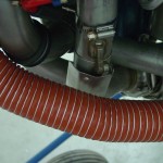
Not really having a specific place I left off, I started by looking over things and making a mental list of things that needed doing.  I decided to have a go at installing the blast tubes for the Pmags.  Dug out the 3/4″ SCAT, cut appropriate lengths, and affixed them to the flanges on the baffles with hose clamps.  The right side has the oil pressure tap elbow right there, so I secured that tube in position with a ziptie around the elbow.  The left side has nothing in the right spot for that, so I made a little holder clip that bolts to the mag hold-down stud, and has a half-circle for the tube to nest in, and a slot for a ziptie to wrap around the tube.  This worked out well, and I would have made one for the right side too, but I don’t think there is enough room to get one in there.  I also made a blast tube for the alternator, but I haven’t yet figured out how to secure it to the alternator itself, nor exactly where it should point.

I’ve decided to mount the current shunt, which I initially left out thinking the VP-X would provide the amps feed to the EFIS.  It does, but the EFIS doesn’t display it on the main screen, nor provide a way to alarm on it; it’s display-only on the VP-X page.  With no indication that this may be forthcoming, I’m opting to install the shunt, which will give me a different type of current reading anyhow; having both available may make it easier to troubleshoot certain types of electrical problems.  (The VP-X will indicate how many amps are being drawn by the electrical systems, and the shunt will indicate hoe many amps are being supplied by the alternator.)  Located and marked the mounting location, and did the inital running of the wire pair that connects the shunt to the EFIS.
Hours: 1.8 | Posted in Electrical, Engine | Comments Off

8th August 2011

More FWF, and flying again

Trimmed the excess from the aft end of the inlet duct, then chipped away the foam and the micro that held it in.  Sanded the inside down, and test-fit it back to the plane to see how it turned out — quite well, actually; the duct lines right up with the airbox.  Eventually, I’ll trim 1/2″ or so off the front of the airbox and attach airseal fabric.  Laid up one ply of 3″ glass tape around the duct on the inside of the cowl to add strength and thickness.  Once that cures, I’ll sand down the excess fabric sticking out the front and shape the nose of the inlet.

While I had the bottom cowl on, fit the top cowl to check fit of the airseal fabric; looking good so far.  I curved it over and added some paperclips to try and train the fabric to bend in the correct direction.  Tied up the engine heater wires behind the sump, torqued the baffle screw behind the dipstick tube, then installed & safetied the dipstick tube.  Plugged in the engine heater and verified it was still functional.


Finally made it to the airport yesterday to go flying with my CFI and get current again.  It came back better than I expected, and he was satisfied enough to sign off on my flight review, which was due at the end of the month.  That stamp says I’m basically safe…now the task is to fly enough to get proficient and fly accurately, then I’ll set up some transition training with one of the CFI’s who does RV-specific training, in preparation for getting this thing off the ground someday.

Milestone: crossed 1500 hours logged on the project tonight.

Hours: 1.9 | Posted in Cowling & Baffles, Engine | Comments Off

5th August 2011

Fiberglass, mostly

More work on the fiberglass stuff…

  • Trimmed yesterday’s layup on the FAB; spread some flox/epoxy into the gap, and added another ply of glass on the inside.
  • Scraped and sanded the epoxy runs off the HS/VS tips; the epoxy isn’t fully cured yet so will wait until later to sand, when it’s harder.
  • Did a little cleanup on the empennage fairing, scraping off the unidentified brown goo splotches from the factory.
  • Tacked the foam block into the cowling snout.


And a bit of non-fiberglass stuff for sanity…

  • Torqued & sealed the fuel hoses at the flow transducer; FWF fuel system now complete.
  • Torqued & sealed the oil cooler lines; oil system now complete.
  • Deburred & dimpled the flanges of everything subpanel & forward…moving toward riveting the top skin.  Also had to remove the canopy pin mechanism, which will be fun to reinstall from under the panel while laying upside down…
  • Removed the camloc strips, deburred and dimpled the attach holes.
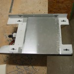
  • Cut a sheet of .020 and bent an angle into the edges, then fit it to the bottom of the fuel pump mounting plate.  Since this piece has a bunch of nutplates on the bottom of it, and many tubes & wires run beneath it, I decided that having a sheet in there would be a good idea to prevent any possible chafing (there is clearance between the plate and the bundles, but just in case, vibration and all that…).  This looks like it will do the job nicely.  It’s tacked to the mounting plate with a blob of Goop at each corner, and one in the center.


Doing some evening reading and working up a list for tomorrow, when I’ll again ignore all the other work that needs to be done to spend the day in the shop.

Hours: 3.4 | Posted in Cowling & Baffles, Engine, Wing & Tail Joins | Comments Off

31st July 2011

Moving day, part the first

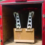
We rented a 12′ trailer after church today (my 10′ is too short) and took the wings to the airport, secured to their cart.  Definitely more space in the shop now, with that missing.  The 11′-something wing cart, seemingly a large piece in the shop, sure looks small in a big hangar.  Allison sees this as a sign the light at the end of the tunnel is approaching, and has visions of her car nestled in the garage this winter.
 

Back home, time to get the rest of this thing finished so it can go to the hangar too…(someday).

Torqued and sealed many of the FWF hoses; the oil lines and connections at the transducer remain.

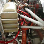
Finished install of the heater SCAT tubing, trimming to length and securing, installed a heat shield on the #2 exhaust pipe where the tubing passes by.

Spent quite awhile sorting out the routing of ignition wires and securing them behind the engine so they’re not rubbing on anything, and have enough slack to account for movement of the engine.  The ignition leads are now complete.

Ovalled an adel clamp and used it as a bracket to hold the battery charger plug near the oil filler, where it can easily be accessed via the oil door.  Trimmed the charger leads shorter and put on new ring terminals; secured the battery cables to the battery.

Cut a new FAB top mounting plate with the fuel servo hole moved as far the to right as it would go; this will help account for the servo’s offset to the left, and give more clearance between the FAB and the cowl.  Fit and drilled the FAB plate to the fiberglass shell, temporary-bolted the mount plate on, then fit that assembly to the engine.  A bunch of iterative fitting & trimming with the bottom cowl ensued to get alignment with the air scoop; I tweaked the front of the top plate, and had to split the fiberglass shell to angle it downward.  That’ll require laying up some glass to bridge the gap.  I drilled the forward part of the box to the plate, to hold it in the correct position.

Hours: 9.5 | Posted in Engine, Plumbing, Wings | Comments Off

30th July 2011

Paperclip trick

Crimped a ring terminal to the buss end of the SD-8 power wire, and secured it to the VP-X stud with the main buss feed.  Verified proper operation of the SD-8 relay.  Loosened the capacitor and relay to allow bucking bar access above them for riveting the top skin.

Back to baffles for a bit; set up a row of paperclips around the sealing edge and put the cowling on; this pushes the paperclips down and reveals the spacing between the baffle edge and the cowl.  Once the cowl is removed, I marked a line 1/2″ down from the top of the paperclips, and used that as a guide to trim the baffles, aiming for the specified 3/8-1/2″ gap.  Rough cut with snips, cleaned up with files, finished with scotchbrite in the die grinder.  Refitting of the cowl revealed a couple small areas that may need a wee bit more trimming or a change in contour, but that’s easy enough to deal with.  Should be ready to cut airseal fabric soon.

I’ve slowly been adding ignition wires as time goes by, so I decided to put the rest of them in, and start work on tying them up.  I sorted out the various lengths and determined which is intended to go where, then started working from the spark plugs aft.  Swapped around some baffle/valve cover screws to get adel clamps installed on the lower screw of each valve cover, to hold the bottom plug wires.  I’m making spacers to secure adjacent wires with zipties and short pieces of silicone tube left over from the manifold pressure plumbing, similar to what’s shown in the Pmag docs.


Also started work on the heater SCAT tubing, and got most of that routing sorted out and tube secured.

Hours: 4.1 | Posted in Cowling & Baffles, Electrical, Engine | Comments Off