28th
March
2011
Some new info on the wiring for the interface between the NavWorx, AFS, and GTX 327 transponder came out, which meant moving one wire and adding another wire, so that’s what I did tonight.
Hours: 2.3 | Posted in Electrical |
27th
March
2011
Worked on a laundry list of essentially small tasks, which filled up most of what turned out to be a fairly productive day. I’m approaching the point where I need to order a bunch of stuff in order to continue installing things (like control cables, exhaust, FWF plumbing, and so on), but that’s likely to be delayed for a few months for finances, and it’s likely that if it’s delayed into May, it’ll be delayed until fall. Oh well…perhaps the summer project will have to be tips, fairings, and wheelpants.
- Finished programming the VP CU and testing electrical continuity and switching to all the devices which are installed. Even plugged one wing in to check out the taxi light, and the wig-wag. The VP config program, along with the Ethernet connection, is pretty slick.
- Fabricated the attach point and pushrod for the flap position sensor; installed the sensor and adjusted the pushrod for appropriate travel. Monkeyed around with the VP flap options, checking out the momentary feature which uses the pos’n sensor to run the flaps to pre-determined stops.
- Fabricated and installed doublers for the comm antennas, which tie into the seat ribs for extra stability. Terminated the L antenna coax and installed both antennas.
- Terminated coax and installed the ADS-B antenna.
- Installed the aileron pushrod boots.
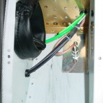
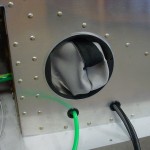
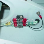
- Made up and installed a wire to tie the shields of the nav/strobe light cables to ground; per AeroLED’s recommendation, these are tied to airframe ground at the terminal block under the LH seat pan.
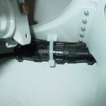
- Installed a tiewrap base to secure the pilot stick grip connector, and secured it.
- Bolted the throttle quadrant to the panel; both the quadrant and the panel now have added stability. This is at least temporarily bolted in place, so I can get an accurate measurement for ordering control cables.
- Swapped out Adel clamps on the center heater control cable, now that I have the correct size on hand.
- Installed an Adel clamp on the parking brake bracket and adjusted the cable end to swing to the correct angles for open/closed.
- Used a pair of Adel clamps to stand-off the parking brake cable from the LH fuel vent line.
- Went on an Adel-clamping marathon FWF, establishing wire runs along the engine mount tubes and getting the sensor wires going in the appropriate directions.
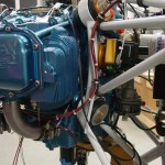
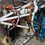
- Installed and safetied the oil temp sensor bushing w/crush gasket, and the oil temp sensor. Wired the sensor.
- Installed the fuel and oil pressure sensors on the sensor manifold, and wired both sensors.
- Wired the manifold pressure sensor.
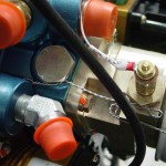
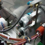
- Wired both Pmags and secured the wires with heatshrink and Adel clamps. Tested power to the Pmags; the LED’s lit up, so I’ll assume it’s good for now. The install docs warn against doing much of anything without the ignition leads connected, so I didn’t put them in “run” position. Tried to install EICad (the Pmag programming software) on my laptop, but the setup program fails; it may not like Windows 7.
- Installed new lockwashers where a couple Pmag mounting nuts had been loosened for access or installation, and torqued.
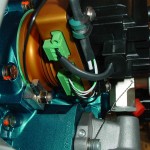
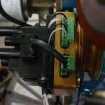
- Temporarily hooked up the power harness for the Reiff engine heater, and plugged it in for a test. It gets warm pretty fast! I know there isn’t much oil in the sump now to heat, but it had the engine case warm, and the cylinders warming, without much delay.
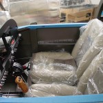
- With the antennas, terminal strips, pushrod boots, etc. in, I shouldn’t need to get under the seat pans for awhile, but it will be nice to sit in the plane to program avionics and check things like rudder pedal location…temporarily installed the seat pans with a reduced number of screws. I’m planning to use stainless button head hex screws and washers on these, so this was a good test of that plan–worked perfectly. I should pick up a set of ball-end hex drivers for doing these in the future. (Note to self: seat pans are reversed, the right one should be on top at the overlap…will reverse when next removed.)
- With the seat pans in, put the seats in (still wrapped in plastic; I’ll also need to pick up some towels or something to protect the seats on ingress/egress). Climbed in and had a sit for a minute…looks like the rudder pedals will need to be at the most fwd position, which surprises me since I’m not terribly long of leg. Might also try the seatback in the aft hinge, but I was pretty comfortable at the angle they were at in the middle hinge.
- Tossed the charger on to top off the battery, as I’ve been running power for periods over the past few sessions of electrical install.
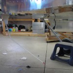
And a couple of “big picture” status shots for those who wonder what the plane actually looks like these days…
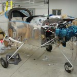
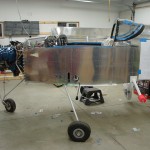
Hours: 9.3 | Posted in Electrical, Engine |
26th
March
2011
Today I installed the real VP CU in place of the blank shell that was used for mounting and wiring, after testing the power to everything that’s installed. (There is a lot of gear that gets power but doesn’t yet exist–ELT, APRS, EFIS’s, 430, and so on…as well as things in the wings that aren’t connected at the moment.) Of course, I discovered that I had stupidly reversed the gender of the DB connectors; I had read the sheet as indicating the cable gender, where it was really indicating the gender on the CU. So, all those pins were cut off and recrimped.
With the connectors sorted, I was able to power up the box and hooked the computer to it to begin programming and testing. Had time to program just a few pins before it was time to go to work.
Hours: 2.1 | Posted in Electrical |
24th
March
2011
Finished pulling the phone and mic lines through the airframe, and soldered them to the corresponding jacks. Terminated the transponder and #2 comm antenna coax and installed the antennas, at least temporarily (they’ll eventually have a bead of sealer underneath). I may end up putting doublers in for the comm antennas, as the skin flexes a fair bit with left/right motion of the antenna.
The audio system essentially complete, I had an urge to test if the jacks were wired correctly. Slid the audio panel and intercom into their trays, hooked up the two test leads from the VP kit to the master buss feed (one at a time, first) and flipped the switch…lit right up, beautiful. Once I had both running together (I knew there must be a reason VP provides two test leads!), I fetched my headset and plugged in. Works like a charm; audio is there, the PTT’s on the stick and the canopy deck work. I had to look up how to adjust the sidetone volume on the SL-40, as it comes set quite loud. Tested the copilot side too, also works. I think I have an old headset knocking around in some random box, I’ll have to pull it out and test it so we can both plug in at once…better than standing around talking to myself on the intercom! I couldn’t remember the AWOS freq for any of the local airports, though I doubt it would have come in anyway (nearest field is ~15 miles away). No music input handy to check that with, so that’ll come later this weekend. No noise heard from the panel or cabin lights, either.
Hours: 3.9 | Posted in Electrical |
22nd
March
2011
Finished up the wiring of the GPS/Icarus distribution block, crimped sockets on the ADS-B wires, and checked through the wirelist for the 430. Everything had been run except the ground wires, which were somehow left out, so I ran those in place. That essentially finishes up all the behind-the-panel avionics wiring, so I went through neatening and putting final wire ties on everything. I still need to terminate the cables to the 430, and run the mic/phone lines aft. Started feeding those through the fuselage, and got as far as the spar before bed called.
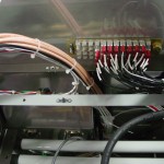
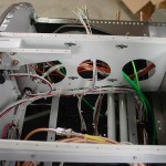
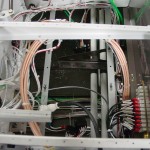
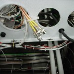
Once those last few wires are in, all that’s left to do electrically is plug in all the boxes and fire it up. Wiring has taken more time that I expected, and it doesn’t look as perfect as I’d hoped, but I enjoy the process and the work, and it’s a bit sad to see the end; though I’m excited to get the AFS screen and light that up. I expect that something will have gone awry and will need troubleshooting, too. Next, it’ll be on to the engine sensors and control cables, which means I should get the exhaust on order (and sort out what prop I’m going to use, so that can be ordered if it has a long lead time!)…but with the avionics purchased, I’m back to waiting for the money tree to bloom before any of that can happen.
Many tie wraps were harmed in the making of this project…
Hours: 3.3 | Posted in Electrical |
21st
March
2011
Decided to go ahead and provision the mounting points for the ADS-B box above the VP CU. I offset the mounting points to the left side, so the units are not centered on one another, to give a better mounting geometry. Two of the bolts for the ADS-B will also penetrate the VP mounting bracket, which will clamp it down even more; those two will need to be removed to remove the VP CU, but the other two will hold the ADS-B box in place while it’s out. Seemed like a reasonable compromise deal, so it’s done. Of course, done in this case just means that the holes are drilled & deburred, and a template made for future use. The nutplates will be installed on the mounting brackets of the box, with hex head screws capturing it from below. I have tried to install everything forward of the subpanel with a mind toward working on it laying under there on my back…no fasteners that need to be access from the top, nothing should needs in-situ soldering to remove, and so forth.
That figured out, I went on wiring the feeds to and from the box; serial to the AFS screen, encoded altitude, antennas, and a serial service port. I’ll need to order another minijack for the service port connection. Ran the power and ground wires, which were the last of the power system wiring, so I started tying up those cable paths.
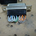
Spent some time working on a distribution “manifold” for GPS signals from the 430, which need to go several places, and the encoded altitude signals (aka Icarus) from the AFS, which also go several places. Wired up a 15-pin D-sub with a series of jumpers to give 4 points for GPS and 3 points for Icarus, and began wiring it in.
Hours: 4.3 | Posted in Electrical |
20th
March
2011
…and still more left to do.
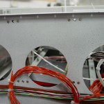
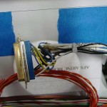
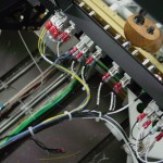
- Pulled in the ARINC lines between the EFIS, autopilot, AP source switch, and 430.
- Wired the autopilot controller connector.
- Drilled a hole, installed a rubber grommet, then wired and installed a mating connector for the GPS 18x. I wanted a connector on the subpanel to allow the canopy to be removed (since the current plan is to mount the GPS on the glareshield), and the connector is also a convenient spot to split the GPS signal out to multiple devices: the EFIS, ELT, and APRS all receive a feed, and another line will run to the 430 location, to feed the devices that will take their GPS signal from the 430 (autopilot, transponder), until the 430 is installed. I put female standoff nuts on the connector, so the connector on the GPS end can be fixed to the subpanel connector. The connector mounts in a rubber bushing to allow it to be pulled out for service when needed, to add or remove a device.
- Re-ran the boost pump annunciator wire using a route that made me happier.
- Decided to locate the ARINC module on the outboard side of the left subpanel rib; this is pretty open from below for access when it comes time to install the module, and I will drill the mounting holes now, install nutplates, and make a template to keep on hand for later, when the box is in hand and brackets need fabrication.
- Ran the wires to the ARINC module location and terminated the module connector.
- Tidied and tied up some wire bundles, most notably everything in the switch row.
Need to figure out if the SL-40 should be receiving any serial feeds; can the AFS push frequencies from it’s database? I don’t have any open serial ports on screen 1, but I have a spare on screen 2, which would allow me to use that feature (assuming it exists) once I have the second screen. Also need to figure out where the ADS-B box will reside and sort the wiring to that. Wondering if I might install rails to mount it above the VP CU, though that’s a lousy spot for accessibility, and worse for installation/removal (at least without pulling the CU first).
Hours: 4.9 | Posted in Electrical |
19th
March
2011
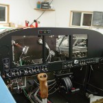
Started the day by removing the panel after marking where the top of the subpanel cutout needed to be. Filed the opening up to the line, and fabricated an angle to reinforce the left side of the cutout. Panel back in, and marked the angle to drill a mounting hole for the SL-40 tray. Primed and painted the angle and riveted it in place, and put in all the panel mounting screws. It’s pretty solid, even without any attachment from panel to subpanel (except via the radio stack).
With the panel in, it’s time to get to work wiring. The rest of the day was spent working on wiring the panel, both to itself and to the airframe. There’s not really much to show, since it doesn’t look much different than it did yesterday.
- Drilled out the pitot heat indicator holes for LED holders and inserted some LEDs. I was originally going to just Goop the LED’s in place, but this allows for the possibility of serviceability, at a minor aesthetic expense.
- All the wiring to the VP CU is complete, except for the backup alternator, since I don’t have that, nor do I know where it will be mounted. The only “flying lead” at this point is for the ARINC converter, as I don’t know yet where that will mount, either.
- The power and grounds are run for the radio stack, and some other connections have been made, such as transponder encoder input and audio from EFIS 1.
- All antenna cables except for the ADS-B and GPS 2 (which is to feed the ADS-B) have their panel ends terminated.
- All the switches are hooked up, as are the annunciator lights.
- The CO/SpO2 sensor’s serial connection is done.
- DB backshells are on the CO detector and both of the VP CU connectors.
- The PTT switches on the canopy decks are connected.
- Airframe autopilot wiring is routed, and a terminal block installed for the power and ground–a single power line feeds both servos plus the control head, so it needed to be split.
- A million zipties, give or take a few, have been installed and cut away.
- Scratched the panel on the upright between the EFIS screens while being (apparently) careless with a screwdriver. Dang. Will have to figure out how to best repaint that segment.
Need to look up a few things, and hopefully will get in a couple hours tomorrow between church commitments.
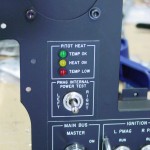
The only picture I managed to take today…
Hours: 10.2 | Posted in Electrical |
18th
March
2011
Some more progress on the panel tonight, things are shaping up nicely.
Installed the LED strips that will provide the backlight for the switch legends. There being no easy way to make a mechanical attachment (riveted Z-clips would work, but that would require more holes through the panel, and I already painted it…), and the LED’s having an extremely long expected lifespan, I clamped the channels to the back of the panel and affixed them with several spots of Goop. After setting, it should provide a solid hold, and still be easily removed if needed for service or replacement of the light strips.
While the glue was drying, I marked and cut the hole in the subpanel that provides room for the radio trays and harnesses to pass through. The right side is quite stiff, as it’s immediately adjacent to the subpanel rib, while the left side is a bit floppy. I’ll run a piece of angle vertically along the left side to reinforce it there, which will also provide a convenient place to tie the radio stack to the subpanel if that appears beneficial. I had to provide a larger cutout above and below the trays that actually penetrate the subpanel (430 & SL-40) — even though the others (audio panel & transponder) are not that long, the bundles of wire exiting their connectors are too close to bend to a central hole. I had previously installed a rubber grommet for that purpose, which is the reason for the half-circle cutout at the top of the stack.
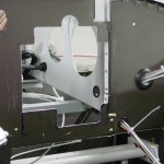
Once the clamps for the backlights were removed from the panel, it was time to fit the radio trays. This was a relatively simple task, since the stack angles were already drilled for the trays and riveted in place. It’s a little tricky to work with nuts & washers in the small space between the left side of the stack and the adjacent EFIS tray, but persistence and appropriate tools pay off. I had picked up a long #1 phillips screwdriver earlier in the day, which came in handy for the skinnier trays; the transponder is a bit taller than the others and a stubby driver will fit inside. I used a square to set the trays perpendicular with the panel face and tightened them down. A test fit of the SL-40 and transponder said that alignment of the faces was still good, and the audio panel tray was adjusted until the gap between it and the SL-40 was equal front-to-back. Once everything was in place, I made some straps to tie the rearward portion of the trays together.
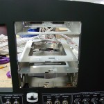
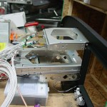
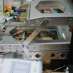
At that point, I had to see if the trays would align with the subpanel cutout, so the whole assembly was set in place on the plane. The cutout was almost perfect, though I need to trim a little more off the top of the large center portion, to ensure that the 430 tray will fit through there when the time comes, without the need to go in and file it out later. The left stiffening angle also needs to be installed. Allison came out to inspect the progress, so I hooked up the light switches and dimmers and we messed around with the lights for a bit. The backlit switch labels turned out exactly as I’d hoped, they look great in the dark.
Hours: 6.5 | Posted in Electrical |
15th
March
2011
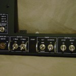
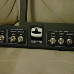
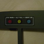
The panel, having sat for a couple days to let the paint cure, was ready to have some parts loaded. The paint turned out alright, though there are a couple blemishes I’m not too worried about them. Took some time tonight to attach the placards, then loaded in the switches, dimmer pots, and annunciator lights, and tightened the nuts down. To finish it off, I loaded in the CO/SpO2 detector, and the blank panels for the autopilot and 2 1/4″ instrument hole. The blanks for the second EFIS and the 430 still need to be fabricated, and the radio trays installed, though I need to cut the subpanel hole as well.
Panel looks pretty good!
Hours: 1.9 | Posted in Electrical |


