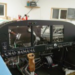
Panel pre-installation
Hours: 6.5 | Posted in ElectricalSome more progress on the panel tonight, things are shaping up nicely.
Installed the LED strips that will provide the backlight for the switch legends. There being no easy way to make a mechanical attachment (riveted Z-clips would work, but that would require more holes through the panel, and I already painted it…), and the LED’s having an extremely long expected lifespan, I clamped the channels to the back of the panel and affixed them with several spots of Goop. After setting, it should provide a solid hold, and still be easily removed if needed for service or replacement of the light strips.
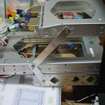
While the glue was drying, I marked and cut the hole in the subpanel that provides room for the radio trays and harnesses to pass through. The right side is quite stiff, as it’s immediately adjacent to the subpanel rib, while the left side is a bit floppy. I’ll run a piece of angle vertically along the left side to reinforce it there, which will also provide a convenient place to tie the radio stack to the subpanel if that appears beneficial. I had to provide a larger cutout above and below the trays that actually penetrate the subpanel (430 & SL-40) — even though the others (audio panel & transponder) are not that long, the bundles of wire exiting their connectors are too close to bend to a central hole. I had previously installed a rubber grommet for that purpose, which is the reason for the half-circle cutout at the top of the stack.
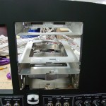
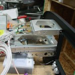
Once the clamps for the backlights were removed from the panel, it was time to fit the radio trays. This was a relatively simple task, since the stack angles were already drilled for the trays and riveted in place. It’s a little tricky to work with nuts & washers in the small space between the left side of the stack and the adjacent EFIS tray, but persistence and appropriate tools pay off. I had picked up a long #1 phillips screwdriver earlier in the day, which came in handy for the skinnier trays; the transponder is a bit taller than the others and a stubby driver will fit inside. I used a square to set the trays perpendicular with the panel face and tightened them down. A test fit of the SL-40 and transponder said that alignment of the faces was still good, and the audio panel tray was adjusted until the gap between it and the SL-40 was equal front-to-back. Once everything was in place, I made some straps to tie the rearward portion of the trays together.
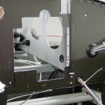
At that point, I had to see if the trays would align with the subpanel cutout, so the whole assembly was set in place on the plane. The cutout was almost perfect, though I need to trim a little more off the top of the large center portion, to ensure that the 430 tray will fit through there when the time comes, without the need to go in and file it out later. The left stiffening angle also needs to be installed. Allison came out to inspect the progress, so I hooked up the light switches and dimmers and we messed around with the lights for a bit. The backlit switch labels turned out exactly as I’d hoped, they look great in the dark.
