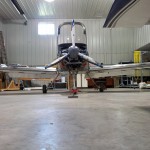
Control the surfaces
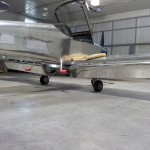
Hours: 8.6 | Posted in Endgame, Wing & Tail JoinsSpent much of the day at the airport, and was able to knock a number of things off the list, some of them pretty big. With today’s progress, the end of the project seems attainable.
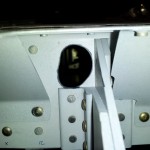
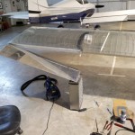
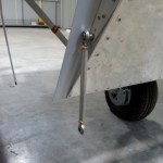
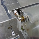
Most of the day spent working on flight controls. First thing to be done was deal with the ailerons, specifically the pushrods. The holes in the rear spar needed to be opened up more to prevent the pushrods from rubbing there, so I carefully enlarged them with files, Dremel and scotchbrite. After several refits of each side, I had it looking decent, and spot-primed the holes and pushrods where the primer had been scratched. While I had the ailerons detached, I also riveted the aileron stops to the hinge brackets.
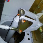
Once the ailerons were installed and secure, I re-checked the rigging that was done during wing building: the length of the bellcrank-to-aileron pushrods. I bolted the jig in place on the bellcrank, and verified that the ailerons were centered on the chord line (marked by tooling holes in the rib). They were, so I moved to the next step — setting the final length of the bellcrank-to-stick pushrods. To do this, I jigged the left bellcrank, and adjusted the pushrod until the stick was vertical. Then, moved the jig to the right bellcrank and adjusted that pushrod, watching for the left aileron to return to it’s jigged position. Once that looked good, I double-checked both sides again by moving the jig from side to side and measuring. When all was tweaked and ready, I tightened down the jam nuts on the pushrod to lock it in place. Then, torqued the bellcrank bolts. Verified that there was “twizzle” (available range of motion in the rod end bearings) in all pushrods at all extremes of travel; we don’t want any of the rod ends to be at the end of their range,which causes a twisting force to be imparted to the pushrod.
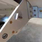
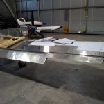
Ailerons done, flaps were next…during installation, I found that a thin strip of aluminum needed to be trimmed from the “ears” at the outboard aft edges of the belly skin, so they did not rub against the flap hinges. Pinned the flaps in place and checked/adjusted the pushrod lengths, then tightened jam nuts and installed to the flap actuator.
I will say that I’m quite happy with the way the control surfaces came out…the ailerons and flaps line up nearly perfectly at the split. Some people have not been so lucky. (Karma being what it is, this means I will have a bear of a time getting the wingtips to fit correctly…)
With all the controls surfaces now installed and rigged, I measured the angular throw on each, and compared it to the design throw in the manual. As the table shows, we’re within spec on most things, and the ones that are out are out by only tenths of a degree:
| Surface | Direction | Design Min | Design Max | Actual |
| Elevator | UP | 25 | 30 | 29.5 |
| DN | 20 | 25 | 21.7 | |
| Elev. Trim Tab | UP | – | 25 | 22.7 |
| DN | – | 35 | 24.3 | |
| Aileron Left | UP | 25 | 32 | 30.9 |
| DN | 15 | 17 | 17.4 | |
| Aileron Right | UP | 25 | 32 | 31.2 |
| DN | 15 | 17 | 17.2 | |
| Flaps | DN | 32 | 37 | 31.9 |
| Rudder | LEFT | 30 | 35 | ~34 |
| RIGHT | 30 | 35 | ~34 |
Lastly for today, spent awhile wrestling with the wing root connectors, to secure them so they don’t flop around during turbulence or maneuvers — both to prevent distress to the wires, and to prevent annoying “clunk” noises in flight. Because the geometry is a little different from side to side (due to my routing of the pitot line), I ended up with different solutions on opposite sides. Both make use of zipties and ziptie bases, and both required alternating between working in the narrow gap between the fuselage and wing with forceps and magic fingers (using the side of the fuselage as a mirror), and shoving my entire arm into the wing through the inboard inspection hole (ow…). I did emerge victorious, if slightly bruised. I like the CPC connectors, but if I were to do it again, I would not use them here. I didn’t realize just how narrow that gap is, and it’s not possible to extract the connector for service or to add pins, etc. I should have used D-subs, a bundle of Molexes, or some other rectangular connector that would fit through the gap (the ones used on the VP system may work). If these connectors ever needs service, it’s likely that I will need to cut them free from the entire bundle and replace them with another type of connector. (Thankfully, I left a service loop on both sides, so that would be possible.)
Two major projects remain: wingtips, and the nosegear. (Plus gear fairings, of course, which will be delayed until after flight.) If I could find a spring scale to buy in town, I think the nosegear would be easy to knock out in a day. After those, it’s just a laundry list of little things to get ready for flight.
