Flaps & gear
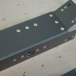
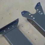
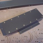
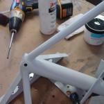
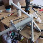
Hours: 6.2 | Posted in Cabin & InteriorNo, it’s not the pre-landing checklist, it’s today’s work session… In the morning, I was able to get the riveting done on all the pieces that were recently primed: the forward tunnel covers, fuel valve cover, and flap parts. Many nutplates were installed, and the flap assembly was clecoed in place for now (still waiting on the missing nutplate to arrive for final install).
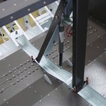
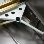
The evening session focused on the next step: gear towers. I ordered a .311 reamer from Avery Tools, which arrived this morning, and was shortly put to use on the gear legs: first, I cleaned the inside of the towers and the outside of the gear legs with a scotchbrite pad, then wiped everything down and coated with some light oil (I just used pneumatic tool oil which I happened to have handy). This allowed them to slide together with relative ease…a couple taps with a rubber mallet and everything was aligned. With Boelube on the reamer and a dab inside the pre-drilled hole, it was easy to ream the hole to size. Disassembled and deburred, and the legs were set aside for later use. The gear towers went into the fuselage, after trimming away a bit of the aft end of the outboard floor stiffeners to allow clearance for the mount.
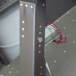
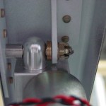
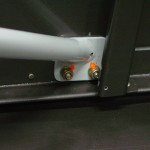
Of note is the brake fitting holes which were drilled back in the bottom skin prep phase…while the right hole aligned well, the left one was off by about 1/3 diameter, compared to the hole in the weldment. Not a big deal, I just used the unibit to move it in the correct direction, large enough that the fitting could slip into place. I also upsized the bolts along the top of the spar to -13A’s, which means I’ll need to order a fistful of -13A replacements…it just looked better, as the nuts have only about 1/2 thread showing with the -12′s. This is apparently a common issue, and other builders have also upsized to the -13A’s, though Van’s says it’s unnecessary. For ease of fitting the gear towers, the outboard snap bushing was also removed, and reinstalled after the towers were bolted in. A long open-end or box-end wrench is a necessity here, to reach the nuts inside the bottom of the spar.
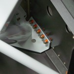
The next step was to drill the holes and install the fasteners along the side skins. The 5 aft bolts are easy; they are drilled using the pre-punched holes in the skin. The 2 forward holes are drilled through the skin using holes in the mount, one of which is tucked in behind a bulkhead flange and not easily accessible. Following the lead of others, I used a #40 bit to drill through the bulkhead flange, then out through the mount and side skin. I enlarged that hole from the outside to #30, then to final size for the AN3 screw, and countersunk. The most difficult part of the operation is fishing the chips out from between the side skin and bottom skin…I made good use of the “chip chaser” tool, along with a thin steel ruler. The left side is drilled, the right side will get done tomorrow.
(An aside: I watched an online EAA video last night about torque seal, and learned that I’d been doing it partially wrong…the torque seal is supposed to be applied from the nut, across the washer, to the base material, but not from the nut onto the threads…apparently it can damage the threads on later removal. I’ve done quite a few with a stripe all the way from the base material to the threads, so if those need to be removed later, the threads will be inspected and replaced as needed.)
