Brackets, and moving parts!
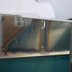
Hours: 10.1 | Posted in Forward FuselageStarted off a day in the shop by finishing up the install of the gear webs and associated brackets & spacers. This seems to be a common area to remake parts, so I studied some other build logs carefully last night, and I believe I got it right, without having to remake any parts. I have not, however, yet located the 426AD3-8 rivets called out — the longest I have in my rivet organizer are -6. So, there’s a search in need of doing.
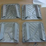
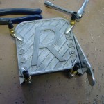
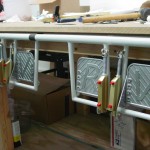
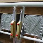
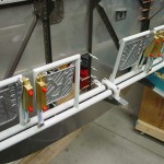
Moving right along, I set out to build the rudder/brake assembly. I’d previously purchased a couple sets of Jim Wright‘s die-cast brake pedals (I am installing dual brakes), and last week I ordered some hardware from McMaster-Carr to install them. I went with stainless hex-head cap screws, but I had to guess at the length–I ordered 5/8″, but it turns out them could have been 1/2″. Something to add to the list for a future order, since they’ll be an easy swap. I also ordered some Oilite bushings for the pedal pivots (p/n 6338K331), along with springs, nylon bushings, and set-screw collars for the brake return springs which are a common mod. (Smitty has the parts list, which I used, and it worked out perfectly.) From Aircraft Spruce, I ordered four AN3-56 bolts, another recommended mod for the brake pedals…those bolts are pricey! I aligned everything with clamps, clamping the whole rudder pedal assembly to the bottom of the workbench, then drilled the brake cylinders to the pedals. With the oilite bushings press-fit into holes in the pedals, the long bolts, and the return springs on the cylinders, the pedals seem to have a nice smooth action.
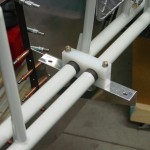
Next, the whole built-up assembly is fit to the fuselage. This sounds easy, but actually requires either a large angle drill, or removal of the auxiliary longerons to which the pedal pivot blocks attach. I chose to remove the longerons, one side at a time, for drilling–after marking the 3″ setback from the firewall. A scrap piece of angle, match-drilled from the UHMW pivot blocks, served as a drill guide. I put in 3 sets of holes — one at the forwardmost location (3″ from the firewall), one which is 3 1/4″ aft of that (so the aft hole becomes the forward hole), and one in the middle of those two. I’m an average-size guy, so I fit them up in the middle set of holes for now.
The last step is adding the center brace. I deburred this piece and cut the relief on the forward side, then clamped it in place and drilled it to the firewall. Marked the location of the pivot block, then removed and drilled. This is a mental exercise, as the hole distance on the bolts for the center pivot is 3″, where the side blocks are 3 1/4″…I failed the test when marking the holes for the forwardmost and rearmost positions, and ended up with slotted holes in those positions. Doesn’t seem like that should be a problem, and if it is, it’s an easy piece to replace. Seeing this assembly in the fuselage was rewarding–the first moving parts on the fuselage. It’s sort of like the moment where you bolt the rudder to the VS for the first time in the empennage build…moving parts are exciting.
Ten pieces left to install (floor stiffeners, and baggage compartment bits) before everything comes apart for oodles of deburring.
