2nd
January
2009
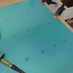
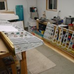
Started the skinning process by clecoing a fishing line to the spar, pulled tightly to show proper alignment of the row of rivet holes. I used a temporary bottle-jack-on-drywall-mud-pail system to raise the sag out, as I forgot to pick up anything to make a more permanent center stand with.
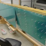
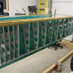
The first step to skinning the wings is to drill the wing walk doublers to the top skins on the bench. The instructions have you drill just three holes per rib, and then drill the rest on the wing. Labelled the parts as they were drilled for left/right and orientation, then proceeded to cleco those pieces to the left skeleton. The structure, which is rather wiggly with just the spars & ribs, really stiffens up with the skins attached. Attached the outboard skins as well, then moved the jack assembly to the right wing and attached the skins there as well before calling it a night.
Passed 200 hours today.
Hours: 1.7 | Posted in Skin Panels |
2nd
January
2009
Completed the riveting of the wing skeletons by attaching the right rear spar to the ribs, and the forward rib tabs to the main spar…easy. I also took a trip to the store for some plywood to reinforce the wing jig, and built that. Ended up making a second trip, too, as I underestimated the amount of threaded rod I’d need to rig up the angles at each side. The threaded rod with nuts at each end allows for an easy adjustment of level.
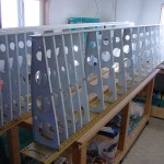
Building up the jig went easily, if not necessarily quickly. I followed the general lead of Smitty, who details the dimensions and such he used in his build log. I built two jigs, so that both wings can be built at the same time. They’re also freestanding, rather than the plans type which have a post running from floor to ceiling; this was essential for me as I need to be able to get the overhead door open, and the posts would interfere. It’s basically 4′ legs, 5′ uprights, and 139″ on the beam, with reinforcing sheet panels (I used some cheap 1/4″ chipboard), angle braces on the uprights, and lots of screws. The arms are made from leftover steel angle bracing from the overhead doors I removed from the shed that we tore down to make way for the new garage…proof that saving everything has its merits! Hung the skeletons on the jigs.
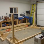
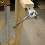
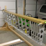
Fixed the heater, as well. The check-valve device turned out to not be the culprit, as the problem continued after I took it out of the line. Pulled the access panel off again and took a good look inside. I saw signs of arcing on the side of the spark igniter arm (two metal rods that stick in through the burner box to create the spark in the jet of gas for ignition). That tipped me off to the trouble; turns out the igniter had a smaller gap to the nearby burner than it did to its own ground rod, which was causing the spark to jump to the burner, rather than the igniter gap–which put it largely outside the gas jet. I removed the igniter assembly and bent the two rods away from the burner a bit, then reinstalled. Perfection. It lights off every time now that the spark is happening in the gas jet, rather than jumping to the metal of the burner.
Hours: 5.0 | Posted in Spars & Skeleton |
1st
January
2009
Started out with a pile of primed parts and spars. Lesson one: remove any blue tape used for masking as soon as possible…I covered the gaps of the upper and lower flanges with tape to keep metal chips from the countersinking from falling in, and ended up spending a fair bit of time removing it, and the adhesive goo it left behind. (Yes, this was the blue, easy-removal “painters” tape.) A heat gun helped more of the adhesive come off with the tape, and acetone cleaned up the rest.
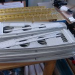
Riveted the rear spar components together to form complete spars; careful attention required here to avoid filling any holes needed for other pieces later on. A close look at the plans in the area of the outboard aileron hinges revealed a previously overlooked detail; that the outboard rib is attached to the rear spar with flush rivets, so the aileron bracket can fit over those rivets. Dimpled the outboard rib, rear spar, and spar doubler on each wing.
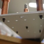
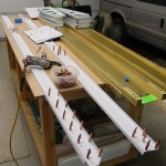
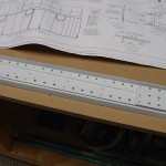
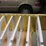
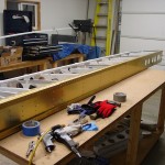
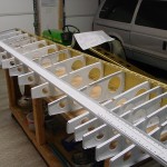
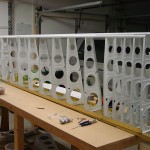
Clamped the left main spar to the bench and attached the ribs one at a time from the outboard end inward, which worked well. Once those were in place, I riveted the front tabs of the ribs which are beneath the fuel tanks to the countersunk holes in the spar. (There’s no specific mention of this in the instructions, but it’s clear from the plans what needs to be done here…whether this was the best time to do it will be decided later.) Clecoed the rear spar to the ribs, and riveted that on–all those rivets are squeezable, which is nice. The right wing has nicer rivets, as I changed the way I was using the rivet gun by lowering the pressure at the compressor regulator, and opening the restrictor on the gun fully. This seemed to provide a more even series of hits than a higher pressure dialed down at the restrictor. (The theory is that because the restrictor controls flow, not pressure, the first hits of the gun are at full line pressure–since the pressure has time to equalize across the restrictor orifice–with subsequent hits at a lower power due to the restricted flow.) Finished the right main spar-to-rib rivets, but still need to squeeze the rib tabs and rear spar attach.
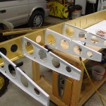
Also getting a little frustrated by the heater…works great when it fires, but it fires very randomly, with many failed ignitions. I’ve checked input pressure and manifold pressure with a simple U-tube manometer, and both look OK. I’m wondering if the saftety check-valve gizmo installed in the line (it came with the CSST that I used to go from the valve to the inlet connection; it’s supposed to close in the event of a breakage of the flex line) is causing a problem. I might remove that from the line and see what happens, and will also double-check the spark ignitor, but it appears to function correctly.
Hours: 7.5 | Posted in Spars & Skeleton |


